Phosphorescent phosphor
a phosphorescent phosphor and phosphorescent technology, applied in the field of phosphorescent phosphor, can solve the problems of chemical instability or poor light resistance of phosphors, and achieve the effect of high afterglow luminan
- Summary
- Abstract
- Description
- Claims
- Application Information
AI Technical Summary
Benefits of technology
Problems solved by technology
Method used
Image
Examples
example 1
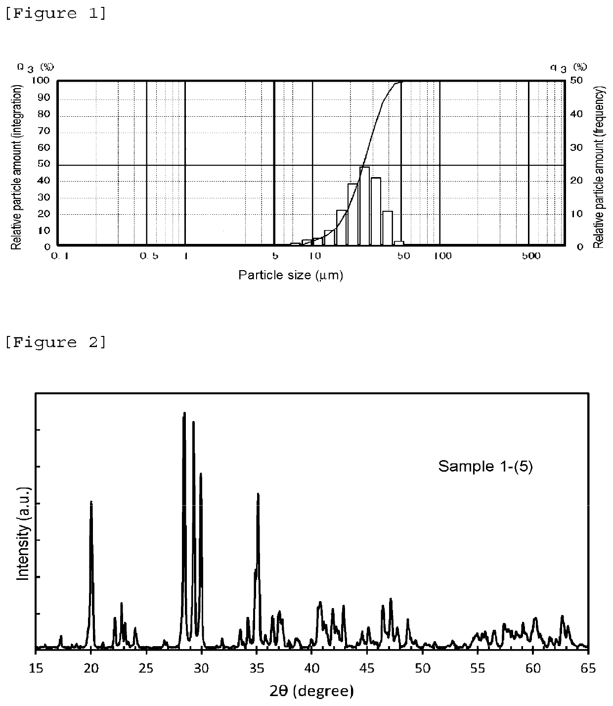
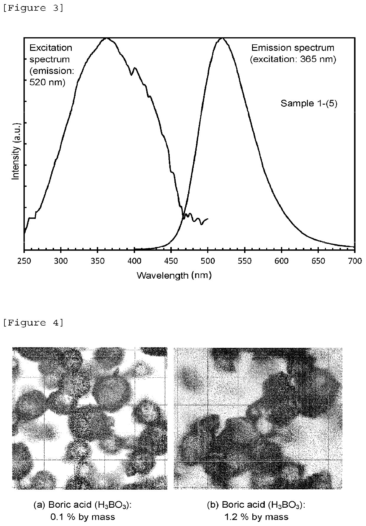
[0028]As the raw materials, the following were weighed: 126.23 g of strontium carbonate (SrCO3) (0.855 mol in terms of Sr); 4.72 g of basic magnesium carbonate (a lot having a MgO content of 42.7% was used) (0.05 mol in terms of Mg); 9.87 g of barium carbonate (BaCO3) (0.05 mol in terms of Ba); 101.96 g of alumina (Al2O3) (2 mol in terms of Al); 2.64 g of europium oxide (Eu2O3) (0.015 mol in terms of Eu); and 5.59 g of dysprosium oxide (Dy2O3) (0.03 mol in terms of Dy). Additionally, as a flux, 0.25 g of boric acid (H3BO3) (approximately 0.1% of the mass of the raw materials, approximately 0.004 mol in terms of B) was weighed. Additionally, 5.3 g of sodium carbonate (Na2CO3) (0.1 mol in terms of Na) was dissolved in water so as for the resulting solution to have a volume of 100 ml, and thus a 1 mmol / ml, in terms of Na, aqueous solution of sodium carbonate was prepared. To these raw materials and the flux, 1.5 ml of the aqueous solution of sodium carbonate (1.5 mmol in terms of Na) w...
example 2
[0045]Samples were synthesized by the same production method as for the sample 1-(5) of Example 1 except that as the carbonates of the alkali metal elements, in place of sodium carbonate (Na2CO3), potassium carbonate (K2CO3), lithium carbonate (Li2CO3) and rubidium carbonate (Rb2CO3) were used and appropriately added as shown in Table 4, and the resulting samples are referred to as the sample 2-(1) to the sample 2-(7), respectively. The content of each of the alkali metal elements was measured by flame photometry in the same manner as in Example 1.
[0046]
TABLE 4SrMgBaEuDyAlkali metalSample(mol)(mol)(mol)(mol)(mol)element (mmol)Comparative0.8550.050.050.0150.03—0Example 1Sample 2-(1)0.8550.050.050.0150.03K0.36Sample 2-(2)0.8550.050.050.0150.03K2.7Sample 2-(3)0.8550.050.050.0150.03Li0.23Sample 2-(4)0.8550.050.050.0150.03Li1.8Sample 2-(5)0.8550.050.050.0150.03Rb0.21Sample 2-(6)0.8550.050.050.0150.03Rb0.98Sample 2-(7)0.8550.050.050.0150.03Na0.97K1.93
[0047]For each of the resulting sample...
example 3
[0051]Samples to which sodium (Na) was added as the alkali metal element were synthesized by the same production method as for the sample 1-(5) of Example 1 except that the amounts of magnesium (Mg), barium (Ba), europium (Eu) and dysprosium (Dy) added were varied as shown in Table 6, and the resulting samples are referred to as the sample 3-(1) to the sample 3-(4), respectively. The content of sodium (Na) was measured by flame photometry in the same manner as in Example 1. Additionally, samples were synthesized on the basis of the same compositions as in the sample 3-(1) to the sample 3-(4) except that sodium (Na) was not added, and the resulting samples are referred to as Comparative Example 3-(1) to Comparative Example 3-(4), respectively.
[0052]
TABLE 6MgBaDyNaSampleSr (mol)(mol)(mol)Eu (mol)(mol)(mmol)Comparative0.9050.020.030.0150.030Example 3-(1)Sample 3-(1)0.9050.020.030.0150.031.2Comparative0.7050.10.150.0150.030Example 3-(2)Sample 3-(2)0.7050.10.150.0150.031.3Comparative0.89...
PUM
| Property | Measurement | Unit |
|---|---|---|
| temperature | aaaaa | aaaaa |
| time | aaaaa | aaaaa |
| temperature | aaaaa | aaaaa |
Abstract
Description
Claims
Application Information
 - R&D
- Intellectual Property
- Life Sciences
- Materials
- Tech Scout
- Unparalleled Data Quality
- Higher Quality Content
- 60% Fewer Hallucinations
Browse by: Latest US Patents, China's latest patents, Technical Efficacy Thesaurus, Application Domain, Technology Topic, Popular Technical Reports.
© 2025 PatSnap. All rights reserved.Legal|Privacy policy|Modern Slavery Act Transparency Statement|Sitemap|About US| Contact US: help@patsnap.com


