
Fluid therapy device

Active Publication Date: 2020-06-09
STROUD KAREN GUTHRIE
View PDF23 Cites 1 Cited by
  • Summary
  • Abstract
  • Description
  • Claims
  • Application Information

AI Technical Summary

Benefits of technology

The fluid therapy system described in this patent has a negative-pressure motor connected to treatment platforms with fluid channels. The treatment platforms are partially enclosed with a pliable material for easy access. The control panel is mounted on the housing and can adjust the fluid movement. The technical effect is a simple yet effective fluid therapy device that can easily be adjusted for different treatment needs.

Problems solved by technology

While the prior art includes solutions for medical treatment relying on vacuum methods (as described above), these systems are not without their flaws.
Even in the clinical setting, but more so in the residential setting, the repeated use of a device relying on such a system is bound to experience loss of operant functionality over time.
Other issues such as system complexity, cost, and user error further illustrate why the known solutions to pain relief and inflammation, particularly in view of vacuum systems, are deficient.

Method used


Image

  • Fluid therapy device
  • Fluid therapy device
  • Fluid therapy device

Examples


Embodiment Construction

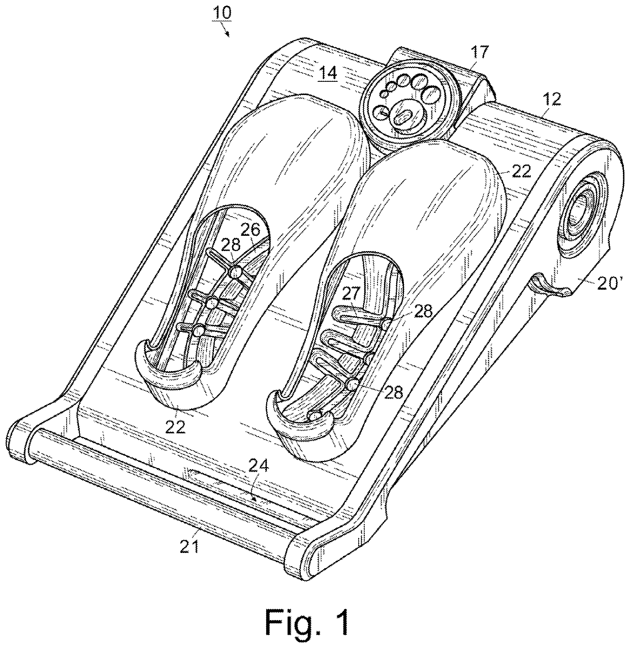
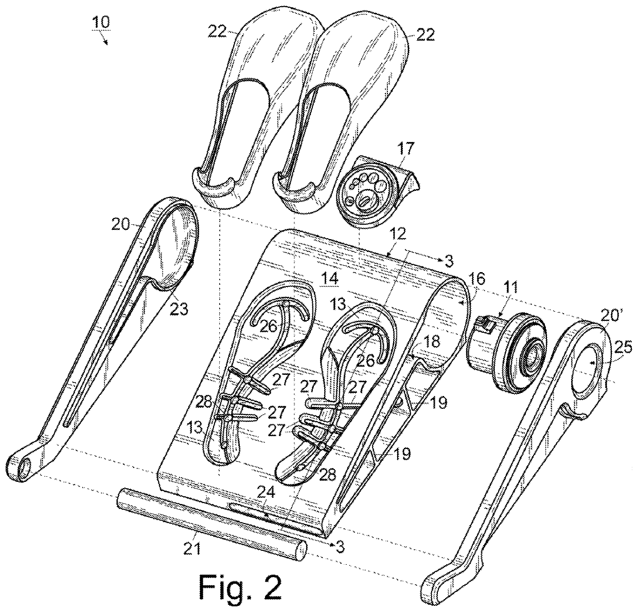
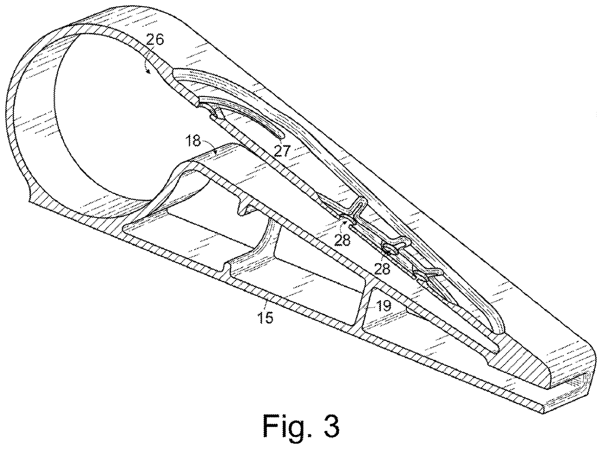
[0016]For a better understanding of the invention and its operation, turning now to the drawings, FIGS. 1-3 illustrate the preferred embodiment of fluid therapy device 10 including negative pressure motor 11 positioned within housing 12 and in fluid communication with one or more treatment platform(s) 13 located on an exterior surface 14 of housing 12. As demonstrated throughout the figures and following description, the preferred embodiment of fluid therapy device 10 is configured (i.e. sized and shaped) to provide treatment to one or both feet of a patient. However, it should be understood that embodiments of fluid therapy device 10 may be configured to treat other areas of the body as well, for example the wrist, the shoulder, the back, the elbow, the neck, and so on.

[0017]Housing 12 is preferably formed from a rigid material such as a polymeric material in the nature of high-density polyethylene, low-density polyethylene, polyvinyl chloride, polyethylene terephthalate, or the li...


PUM


Abstract

A high-velocity fluid therapy device including a negative-pressure source positioned within a housing with a pair of opposingly oriented sidewalls connected by a laterally extending dowel. The negative-pressure source is in fluid communication with one or more treatment platforms, each platform having one or more longitudinally oriented fluid channels and one or more laterally oriented fluid channels. The channels and conduits permit the airflow pulled by the negative-pressure source to pass over the treatment surface, into the channels and conduits, and eventually internalized by the fluid therapy device to reduce the surface temperature of the treatment area, reducing swelling and inflammation, resulting in reduced pain experienced at the treatment site.

Description

FIELD OF THE INVENTION[0001]The invention herein pertains to relief systems generally and particularly pertains to a manifold system for applying fluid stimulus to the exterior surface of the foot, back, or other body part needing treatment.DESCRIPTION OF THE PRIOR ART AND OBJECTIVES OF THE INVENTION[0002]Clinical studies and practice have shown that providing a reduced pressure in proximity to a tissue site augments and accelerates the growth of new tissue at the tissue site. The applications of this phenomenon are numerous, but application of reduced pressure has been particularly successful in treating inflammation and wounds. This treatment (frequently referred to in the medical community as “negative pressure wound therapy,”“reduced pressure therapy,” or “vacuum therapy”) provides a number of benefits, which may include faster healing and increased formulation of granulation tissue. For an example of this type of system, see U.S. Pat. No. 8,313,449 to Hardman et al., entitled F...

Claims


Application Information

Patent Timeline
IPC IPC(8): A61F7/00A61H9/00A61H1/00
CPCA61F7/0085A61H9/0071A61H9/0057A61H1/008A61F2007/0064A61H35/006A61H2201/0214A61H2201/1642A61H2205/12
Inventor STROUD, JR., SAMUEL J.
Owner STROUD KAREN GUTHRIE
Learn More