High shear thin film machine for dispersion and simultaneous orientation-distribution of nanoparticles within polymer matrix

a nanoparticle and polymer matrix technology, applied in the direction of mixing, transportation and packaging, rotary stirring mixers, etc., can solve the problems of poorer performing systems, agglomeration of harnps reduces the effective aspect ratio of nanoparticles and available surface for interaction, and most polymer matrices and nps are not compatible with each other, so as to improve or overcome the deficiencies of the art

Active Publication Date: 2020-06-09
SOUTH DAKOTA BOARD OF REGENTS
View PDF73 Cites 1 Cited by
  • Summary
  • Abstract
  • Description
  • Claims
  • Application Information

AI Technical Summary

Benefits of technology

[0023]It is another object, feature, and / or advantage of the present disclosure to simultaneously achieve high degree of dispersion and orientation of HARNPs within a polymer matrix. The high shear thin film machine (HSTFM) can work with any viscous medium such as molten thermoplastics, liquid thermosets, and oil, because the higher viscosity enables greater transfer of the shearing forces to the agglomeration.
[0032]It is another object, feature, and / or advantage of the present disclosure to control the temperature in mixing region and minimize viscous heat degradation.

Problems solved by technology

By contrast, low aspect ratio NPs (e.g., nanorods, polyhedral oligomeric silsesquioxanes (POSS), silica spheres) have fewer surface interactions to break, resulting in poorer performing systems.
Agglomeration of HARNPs reduces the effective aspect ratio of the nanoparticles and available surface for interaction.
A central issue is that most polymer matrices and NPs are not compatible with each other.
The functionalization with surfactants, however, can have disadvantageous environmental impacts.
The melt mixing methods are attractive due to being environmentally friendly, inexpensive, and continuous, but these methods lack the ability to disperse or orientate NPs, thus requiring the need for additional processing.
The solution mixing methods are discontinuous and environmentally unfriendly.
However, these fabrication methods have not been able to achieve NCs with the extent of theoretically predicted superior properties due to inadequate dispersion of agglomerated NPs as well as inadequate orientation of the NPs in the NC.
The two-roll mill is not suitable for production at industrial scale due to its difficulty to scale up and continuously processing with thermoplastic NCs.
Single-screw extruders cannot provide sufficient dispersion in nanoscale even at low concentrations of weight percent of NPs, because of its low shear rate.
Despite literature indicating that twin-screw extruders are the best dispersing machines among melt mixing techniques, the twin-screw extruders can only partially exfoliate or only disperse nanoparticles within polymer matrix.
Thus, the single screw extruder is not an efficient dispersive mixer because of insufficient high shear regions.
In-situ and ultrasonication dispersion methods are not desirable from an environmental point of view.
Melt mixing dispersion levels are lower than those obtained through ultrasonication and in-situ polymerization because of the insufficient shear rate.
Nevertheless, as mentioned earlier, these methods cannot work with high viscosity molten polymers.
The NCs that are fabricated by current methods have not exhibited the extraordinary mechanical and conductive properties due to poor dispersion of the NPs.
However, the hydrodynamic shear force is only suitable for dispersion of NPs agglomerations when viscosity is high.
Dispersion of NPs within the polymer matrix is a complicated process because of the high viscosity of polymers, interfacial surface incompatibility between polymer matrix and NPs, and NP agglomeration.
And if turbulent flow is created polymer degradation will occur due to viscous dissipative heating and the difficulty in removing the heat from the system.
However, none of these methods have produced a NC with properties close to the theoretical mechanical and functional property limits.
Other methods such as electric and magnetic fields and shear flow orientation methods can produce two dimensional films or three dimensional bulk NCs; however, these fabrication methods have not yet reached practical usage.
Achieving FDSLSF is complicated due to surface roughness at the nanoscale.
Therefore, revolutionary progress in CNT application can only be realized when a technique is developed for the dispersion of the entangled CNTs and then controlling the dispersed CNTs orientation within the PNCs.

Method used


Image

  • High shear thin film machine for dispersion and simultaneous orientation-distribution of nanoparticles within polymer matrix
  • High shear thin film machine for dispersion and simultaneous orientation-distribution of nanoparticles within polymer matrix
  • High shear thin film machine for dispersion and simultaneous orientation-distribution of nanoparticles within polymer matrix

Examples


Embodiment Construction

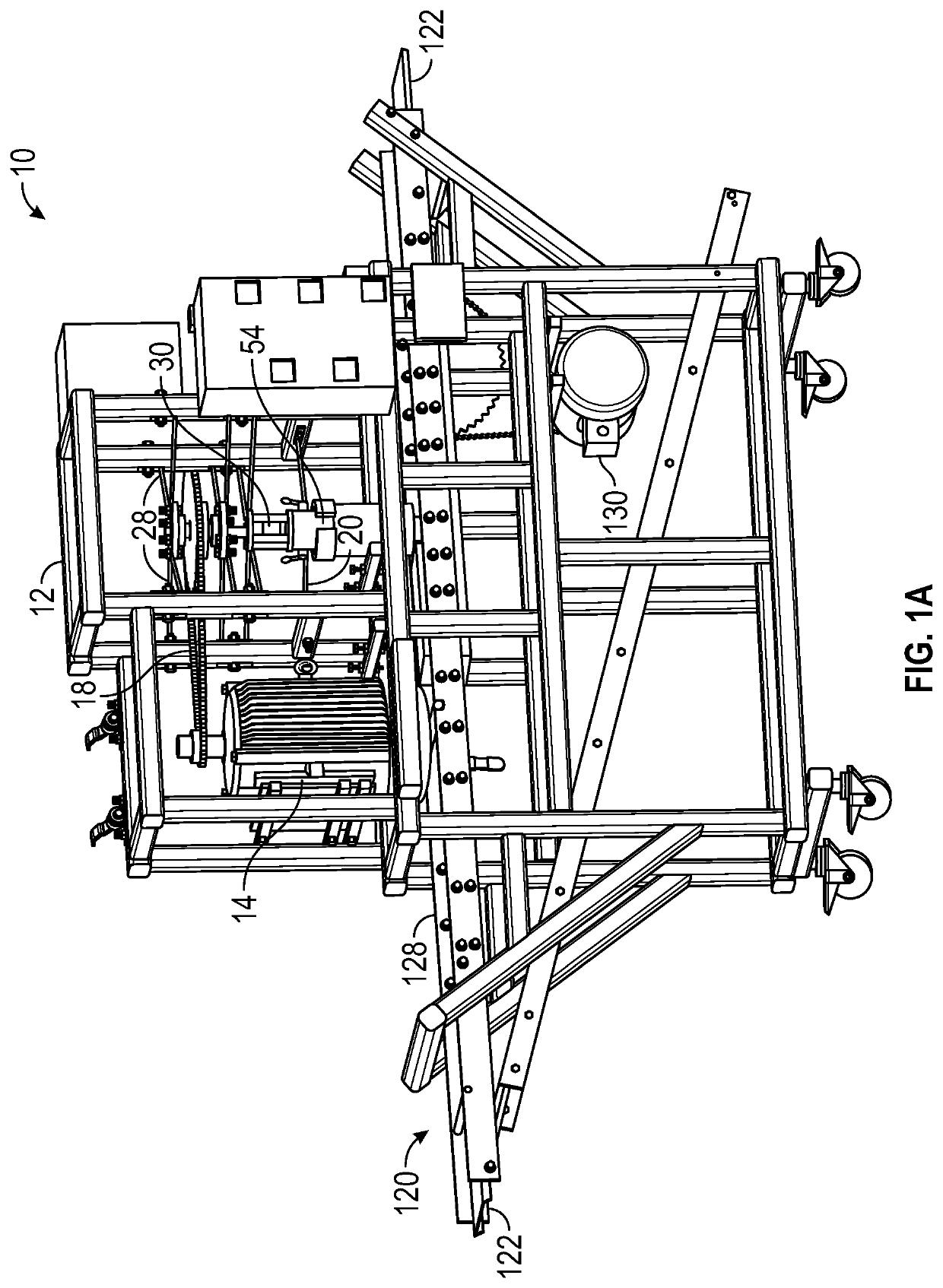
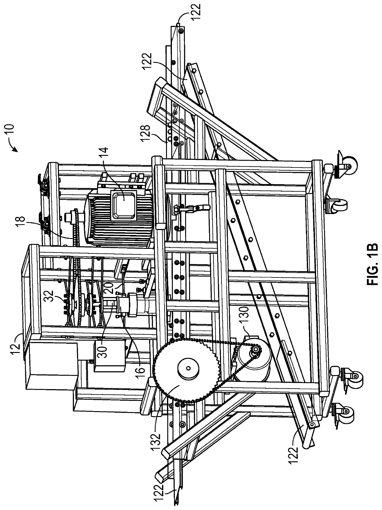
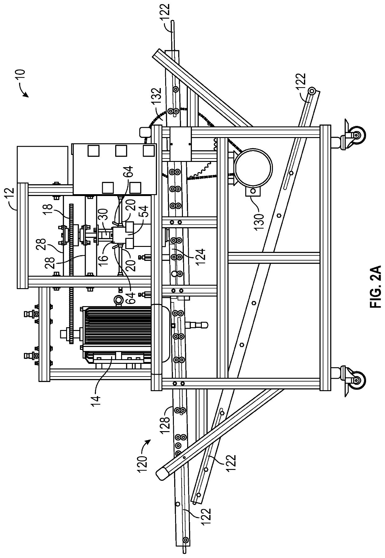
[0077]FIGS. 1A, 1B, 2A and 2B illustrate a high shear thin film machine 10 in accordance with an exemplary embodiment of the present disclosure. The machine 10 includes a frame 12 upon which the components of the machine 10 are mounted. The present disclosure, however, contemplates that the components may be installed on any suitable structure or surface to achieve the objects of the invention.

[0078]A motor 14 mounted on the frame 10 is operably connected to a mixer 16. A preferred embodiment includes a high horsepower electric motor, but the present disclosure contemplates the motor 14 may be powered by petrochemical, solar, stream, and the like. In the exemplary embodiment depicted in FIG. 1, the motor 14 is connected to the mixer 16 through a chain 18. The present disclosure envisions other means of connection, including belts, cables, gear box, and the like. In an alternate embodiment, the output shaft of the motor 14 may be coupled directly to the mixer 16, thereby eliminating ...


PUM

PropertyMeasurementUnit
particle sizeaaaaaaaaaa
aspect ratioaaaaaaaaaa

Abstract

An improved a device and method for dispersion and simultaneous orientation of nanoparticles within a matrix is provided. A mixer having a shaft and a stator is provided. The shaft may have a rupture region and erosion region. Further, an orienter having an angled stationary plate and a moving plate are provided. The nanoparticles and the matrix are fed into the mixer. A rotational force is applied to the shaft to produce shearing forces. The shearing forces disperse and exfoliate the nanoparticles within the matrix. The dispersed mixture is outputted onto the moving plate. The moving plate is forced across the angled stationary plate to produce fully developed laminar shear flow. The fully developed laminar shear flow or the two-dimensional extensional drag flow orients the dispersed nanoparticles-matrix mixture.

Description

FIELD OF THE DISCLOSURE[0001]The present disclosure relates generally to improved nanocomposites. More particularly, but not exclusively, the disclosure relates to the simultaneous dispersion and orientation of nanoparticles within a polymer matrix during fabrication of polymer nanocomposites.BACKGROUND OF THE DISCLOSURE[0002]The use of composite materials is commonplace in today's manufacturing industry. Composite materials advantageously display certain desired physical and / or chemical properties different from the constituent materials. Recent advances in materials science have included development of polymer nanocomposites (PNCs). In the broadest sense, PNCs are comprised of a polymer matrix reinforced with nanoparticles having dimensions less than one hundred nanometers, but often in the range of one to fifty nanometers.[0003]PNCs differ from conventional composite materials due to, among other features, a high surface area to volume ratio between the polymer and the nanopartic...

Claims


Application Information

Patent Timeline
Patent Type & Authority Patents(United States)
IPC IPC(8): B01F7/00B01F3/14B82Y40/00C08J3/20C08J5/00B01F15/06B01F23/57
CPCB82Y40/00B01F3/14C08J3/203B01F15/065B01F7/00816C08J5/005B01F2215/0049B01F2015/061C08J2300/00B01F23/57B01F27/2722B01F2035/98B01F35/92B29C48/834B01F2101/2805
Inventor DASH, ILCHGERELWINTER, ROBB M.
Owner SOUTH DAKOTA BOARD OF REGENTS
Why Eureka
Try Eureka