Inter-stage cooling for a turbomachine

a technology of turbomachines and inter-stage cooling, which is applied in the direction of engines/engines, stators, engine fuctions, etc., can solve the problems of increasing the risk of hot gas ingestion in the front of the well, reducing the quantity available for combustion, and increasing the clearance and redistributing

Active Publication Date: 2020-06-16
ROLLS ROYCE PLC
View PDF19 Cites 0 Cited by
  • Summary
  • Abstract
  • Description
  • Claims
  • Application Information

AI Technical Summary

Benefits of technology

[0011]In accordance with the invention there is provided an apparatus for controlling flow of coolant into an inter-stage cavity of a turbomachine, the cavity bounded by a first turbine stage, a second turbine stage axially displaced along a common axis of rotation with the first turbine stage, and an annular platform bridging a space between the axially displaced first and second turbine stages, an annular plenum chamber arranged inboard of the annular platform, the annular plenum chamber having one or more inlets for receiving coolant and one or more outlets exiting into the cavity, whereby, in use, coolant is delivered into the cavity with minimal pressure loss.
[0016]In some embodiments, the outlet holes may be provided in the form of inserts incorporated into a wall of the plenum chamber. For example, such inserts may be welded or brazed into slots or holes included in the wall, alternatively they might be mechanically fastened. The inserts may be built using an additive manufacturing method. For example, but without limitation, the inserts may be built using direct laser deposition (DLD). An advantage of the inserts is that they may be made thicker than the wall of the plenum chamber allowing the thickness (and hence weight) of the plenum chamber walls to be minimised.
[0017]By using an additive manufacturing process versus drilling, much greater design freedom for the outlet geometry is provided. Any insert may include one or more outlets which may have the same or different geometries. In some inserts, an outlet is provided with a smoothly curved entrance. In some inserts the hole has a vane shaped cross-section. In some inserts the hole follows a spiral path from its entrance to its exit
[0020]A seal may be formed integrally with a wall of the annular plenum chamber, for example a discourager seal may be formed integrally with a radially extending wall of the plenum chamber, the discourager seal comprising an axially extending rim. The discourager seal may extend axially upstream. The axially extending rim may include two or more radially outboard circumferential ribs defining a U shaped cross section of the axially extending rim. The U-shaped cross section serves, in use, as a damping cavity, damping peak pressures whereby to minimise ingestion of hot gas into the cooling cavity.

Problems solved by technology

This drainage of compressed air reduces the quantity available for combustion and consequently, engine efficiency.
Thus, as engines complete more and more service cycles and the inter-stage seals tend to wear there is also an increase in the clearances and redistributing the normally fixed level of coolant flow towards the rear stator well.
This increases the risk of hot gas ingestion in the front of the well.
With ever increasing engine size and higher operating temperatures and engine speeds, pressure losses in the air system increase and coolant flows become less effective and more difficult to control.

Method used


Image

  • Inter-stage cooling for a turbomachine
  • Inter-stage cooling for a turbomachine
  • Inter-stage cooling for a turbomachine

Examples


Embodiment Construction

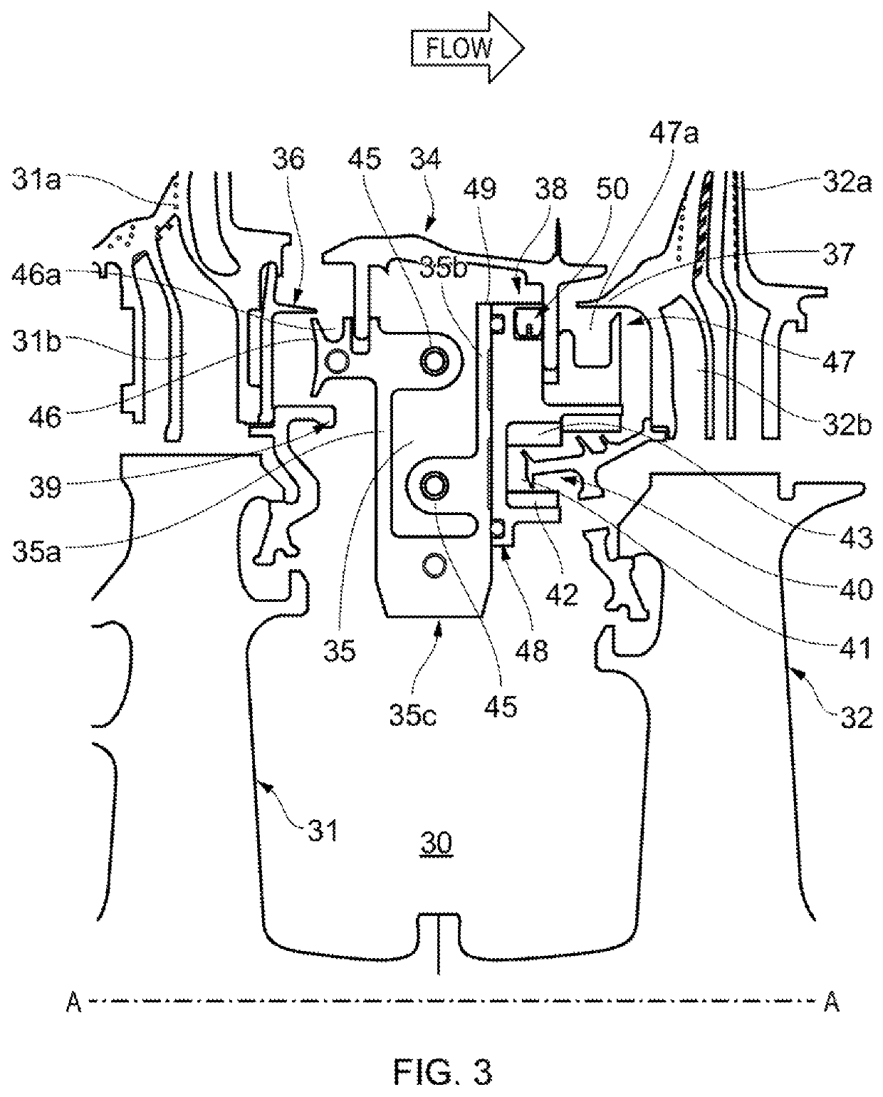
[0035]As shown in FIGS. 3 and 4, a first turbine stage disc 31 is separated from a second turbine stage disc 32 by an inter-stage cavity 30. Each disc carries a blade 31a, 32a and the blades and discs are arranged for rotation around an engine axis A-A. Roots of the blades 31a, 32a contain cooling channels 31b, 32b which receive cooling air from neighbouring, upstream cavities. Blade 32a receives coolant from cavity 30 which sits immediately upstream of the disc 32. An axial gap between the blades 31a and 32a is bridged by an annular platform 34. Extending radially inboard of the annular platform 34 is an annular plenum chamber 35 bounded by the annular platform 34, radially extending walls 35a, 35b and radially inner annular wall 35c. Rim seals 36 and 37 extend axially from roots of the blades 31a, 32a and radially inwardly of the annular platform 34. An inter-stage seal assembly 38 sits immediately downstream of the annular plenum chamber 35. A rim seal 39 bridges a radial space b...


PUM


Abstract

An apparatus for controlling flow of coolant into an inter-stage cavity of a turbomachine is described. The cavity is bounded by a first turbine stage, a second turbine stage axially displaced along a common axis of rotation with the first turbine stage, and an annular platform bridging a space between the axially displaced first and second turbine stages. An annular plenum chamber is arranged inboard of the annular platform, the annular plenum chamber having one or more inlets for receiving coolant and one or more outlets exiting into the cavity, whereby, in use, coolant is delivered into the cavity at an increased pressure compared to coolant entering the plenum chamber at the inlet. The apparatus is beneficially arranged immediately upstream (with respect to the flow of a working fluid through the turbomachine) of an inter-stage seal assembly.

Description

FIELD OF THE INVENTION[0001]The present invention relates to cooling between stages of a turbomachine. For example, but without limitation, the invention is concerned with inter-stage cooling between turbine stages in an axial flow gas turbine engine.BACKGROUND TO THE INVENTION[0002]FIG. 1 shows a gas turbine engine as is known from the prior art. With reference to FIG. 1, a gas turbine engine is generally indicated at 100, having a principal and rotational axis 11. The engine 100 comprises, in axial flow series, an air intake 12, a propulsive fan 13, a high-pressure compressor 14, combustion equipment 15, a high-pressure turbine 16, a low-pressure turbine 17 and an exhaust nozzle 18. A nacelle 20 generally surrounds the engine 10 and defines the intake 12.[0003]The gas turbine engine 100 works in the conventional manner so that air entering the intake 12 is accelerated by the fan 13 to produce two air flows: a first air flow into the high-pressure compressor 14 and a second air flo...

Claims


Application Information

Patent Timeline
Patent Type & Authority Patents(United States)
IPC IPC(8): F01D5/08F01D11/00F01D9/04F01D9/06
CPCF01D5/082F01D5/081F01D11/001F01D9/041F01D9/065F05D2260/20F05D2240/128F05D2240/24F05D2220/32F05D2240/55
Inventor SEHRA, GURMUKH S.THATCHER, PHILIP D.GARDNER, IAIN C.
Owner ROLLS ROYCE PLC
Why Eureka
Try Eureka