Ranging apparatus and moving object capable of high-accuracy ranging

a technology applied in the field of ranging apparatus and moving objects, can solve the problem of lowering the accuracy of ranging at the long distance end of the distance measurement range, and achieve the effect of suppressing the reduction of ranging accuracy

Active Publication Date: 2020-06-23
CANON KK
View PDF21 Cites 14 Cited by
  • Summary
  • Abstract
  • Description
  • Claims
  • Application Information

AI Technical Summary

Benefits of technology

[0007]The present invention provides a ranging apparatus and a moving object which are capable of suppressing the reduction of ranging accuracy at a long distance end of a distance measurement range, thereby making it possible to perform high-accuracy ranging over a wide distance range.
[0011]According to the present invention, it is possible to suppress the reduction of ranging accuracy at the long distance end of the distance measurement range, thereby making it possible to perform high-accuracy ranging over a wide distance range.

Problems solved by technology

However, since in the triangulation, the accuracy of measurement of distance (hereinafter referred to as the “ranging accuracy”) is reduced in proportion to approximately the square of a distance to an object, there is a fear that the ranging accuracy is lowered at a long distance end of the distance measurement range.

Method used


Image

  • Ranging apparatus and moving object capable of high-accuracy ranging
  • Ranging apparatus and moving object capable of high-accuracy ranging
  • Ranging apparatus and moving object capable of high-accuracy ranging

Examples


Embodiment Construction

[0027]The present invention will now be described in detail below with reference to the accompanying drawings showing embodiments thereof. The component elements described in the embodiment are only described by way of example, and are by no means intended to limit the scope of the present invention to them alone.

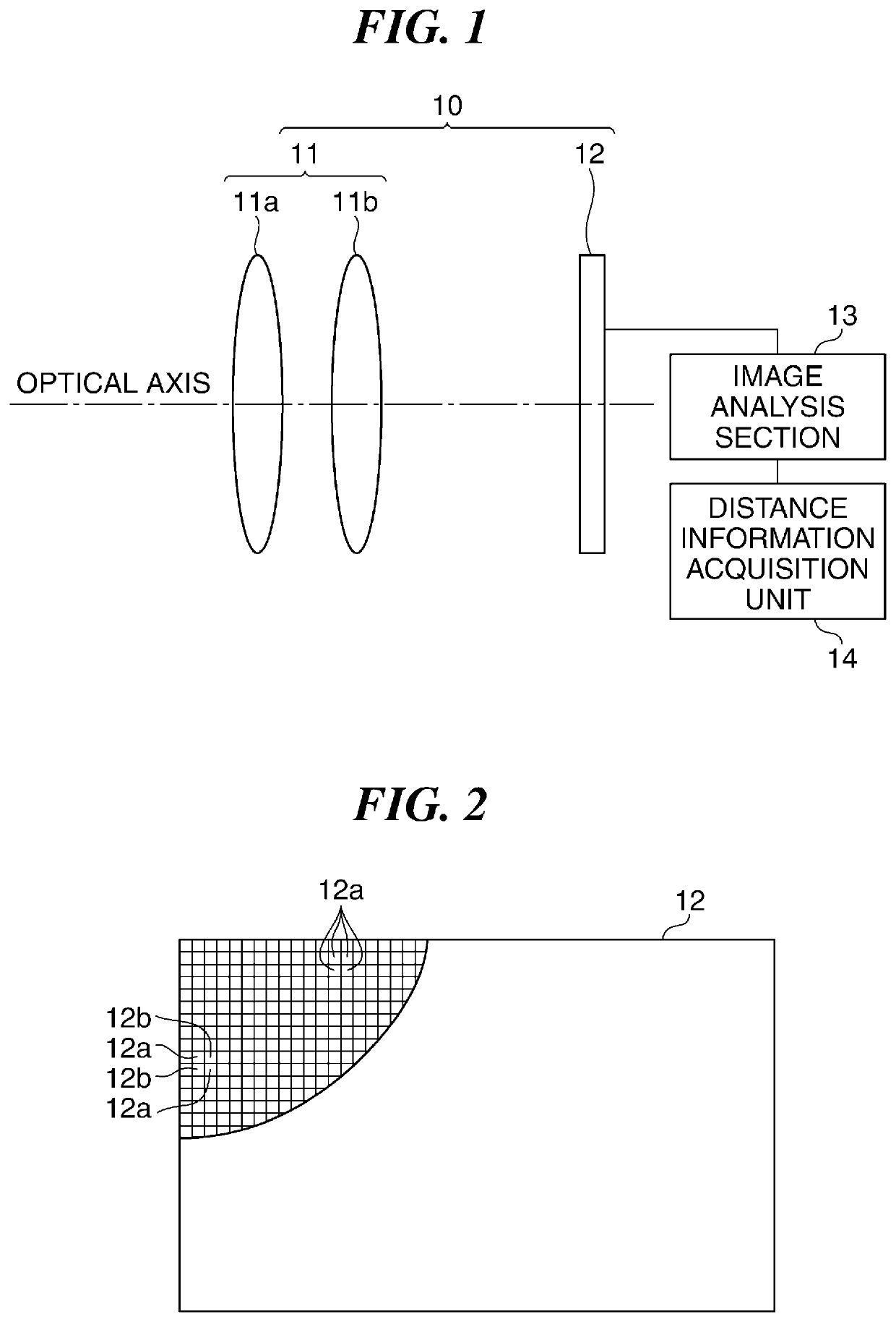
[0028]First, a description will be given of a first embodiment of the present invention. FIG. 1 is a schematic block diagram of a ranging apparatus according to an embodiment of the present invention.

[0029]Referring to FIG. 1, the ranging apparatus is comprised of a camera 10 which includes an optical system 11 as a fixed focus optical system and an image pickup device 12 having a large number of pixels arranged therein, an image analysis section 13, and a distance information acquisition section 14. The optical system 11 includes, for example, two lenses 11a and 11b arranged along the optical axis, and forms an image of an object on the image pickup device 12. As shown in ...


PUM


Abstract

A ranging apparatus capable of suppressing reduction of ranging accuracy at a long distance end of a distance measurement range, thereby making it possible to perform high-accuracy ranging over a wide distance range. An image pickup device receives light fluxes from a fixed focus optical system. A distance information acquisition unit acquires distance information of an object based on image signals from the image pickup device. This section acquires the distance information based on parallax between a first image based on a light flux having passed a first region of an exit pupil, and a second image based on a light flux having passed a second region of the exit pupil. The optical system is configured such that parallax of an object existing at a predetermined distance is smaller than parallax of an object existing at a shorter distance than the predetermined distance.

Description

BACKGROUND OF THE INVENTION[0001]Field of the Invention[0002]The present invention relates to a ranging apparatus and a moving object, and more particularly to a ranging apparatus and a moving object which are capable of performing high-accuracy ranging by an imaging plane phase difference method.[0003]Description of the Related Art[0004]To assist the movement of a moving object, such as a vehicle, a drone, or a robot, it is required to measure a distance between a moving object, and an object, such as an obstacle, around the moving object. Particularly, to assist the movement of the moving object e.g. for avoiding collision or for tracking another object, it is also required to perform recognition processing using images of an obstacle, and hence, a camera as an image pickup apparatus is often used in the moving object, for measuring a distance to the obstacle. As a method of acquiring not only images but also distances using a camera, there has been known an imaging plane phase di...

Claims


Application Information

Patent Timeline
Patent Type & Authority Patents(United States)
IPC IPC(8): G01C3/08G06K9/00
CPCG01C3/085G06K9/00805G06V20/58
Inventor TAKAGI, AKINARINOBAYASHI, KAZUYA
Owner CANON KK
Why Eureka
Try Eureka