Device for conveying fuels into a gasification reactor

a gasification reactor and fuel technology, applied in the direction of combustible gas production, lighting and heating apparatus, combustion types, etc., can solve the problems of screw conveyors that are difficult to cool, screw conveyors are susceptible to breakdown, and the air is difficult to be properly excluded

Active Publication Date: 2020-06-30
CARE BETVERWALTUNG
View PDF15 Cites 0 Cited by
  • Summary
  • Abstract
  • Description
  • Claims
  • Application Information

AI Technical Summary

Benefits of technology

[0011]The invention achieves this aim by proposing a conveying apparatus for gasification reactors of the type described above in which essentially, the conveying apparatus is formed by a hydraulically drivable plunger which is movably guided in a first, cylindrical section of the conveying pipe, and in that the conveying pipe has an internal cross-section which reduces continuously in the direction of conveying the fuel in order to form a compacting cone in a second axial section. Preferably, the compacting cone is located in the last third of the second conveying pipe section in the direction of conveying. The invention therefore proposes hydraulic conveying, which has the advantage of low maintenance costs with a high availability and in addition, with uniform dosing. The hydraulic drive allows greater forces to be applied in the conveying direction so that, for example in the case of a gasification reactor of the type described in AT 405937 B, the fuel can be forced into the upper surface of the bed of fuel, whereupon good mixing is ensured in the fluidized bed and pulsing in the gasification chamber is avoided. In this manner, the fuel is thus conveyed continuously at a uniform rate during the forward stroke. The rearward stroke of the plunger is then carried out at a higher speed in order to get to the next conveying cycle without too great an interruption.
[0013]Further, the hydraulic conveying apparatus of the invention can be used to exclude air from the gasification chamber in a simple manner, which in particular is reinforced by the compaction of the fuel in the compacting cone. The exclusion of air is an essential factor to the quality of the gasification process. The compacting cone is an important component of the gasification device since, by making the opening cross section smaller, it adjusts the compaction pressure or it enables a diminution of the air gaps of the various types of fuel. In this manner, the compaction pressure is also vital as regards the purity and quality of the gas produced in the gasification reactor. Because of the high compaction of the fuel, a plug of fuel is produced inside the conveying pipe which constitutes an excellent and reliable means of excluding air.
[0016]When the exchangeable pipe portion or the compacting cone opens directly into the gasification reactor the second conveying pipe section comprising the compacting cone can be advantangeously connected to the infeed opening of the gasification reactor by interposing a fitting. A fitting of this type is intended to protect the front of the compacting cone against excessive a heat load. This is of particular advantage when the cone is at the height of a fluidized bed of the gasification reactor where a radiative temperature of 850-950° C. can be expected. The fitting also serves to provide a transition between the compacting cone, the opening diameter of which is a function of its cone angle, and the infeed opening of the gasification reactor. Thus, each different cone has a respective fitting. The combustible material is conveyed out of the compacting cone via the fitting into the gasification reactor, wherein the fitting may have an internal diameter which increases in the direction of conveying in order to provide a continuous transition to the internal diameter of the infeed opening of the gasification reactor.
[0023]In order to reduce the overall length of the plunger or the hydraulic cylinder forming the drive for the piston, the front face of the plunger is preferably formed as a part of the plunger which can be extended in the conveying direction. In this manner, the plunger can be extended if necessary. Extending is, for example, carried out with the aid of a hydraulic cylinder housed in the plunger. In normal operation, i.e. for continuous conveying of the fuel, the plunger is operated in the non-extended state. Only for the emptying stroke, during which the fuel in the conveying system has to be discharged to beyond the adapter as far as possible, will the length of the plunger be extended by extending the extendable front portion, for example by 500-1000 mm. Thus, during the emptying stroke, the guiding stability of the plunger is improved. To commence the emptying stroke, the plunger initially runs through its maximum working stroke in the conveying direction until the plunger arrives under the bulk material container, in order to completely block off the ingress of fuel into the conveying pipe. Thereafter, the extendable front portion of the plunger is automatically extended in order to remove fuel, which is still in the conveying pipe until a short plug is left. After the plunger has moved back, the shut-off valve can be closed in order to start inerting or shutting the unit down.
[0024]For continuous conveying of the fuel, it is vital that the fuel does not agglomerate in the bulk material container and does not tend to bridging, thereby preventing the fuel from falling out of the bulk material container under gravity and thus preventing discharge into the conveying pipe. The discharge is basically promoted, if, as in accordance with a preferred embodiment, the bulk material container comprises a discharge hopper. In this regard, the fuel should be comminuted into particles of approximately 4 to 5 cm in diameter in order to prevent bridging in the bulk material container and also to prevent blockages when conveying with the plunger. In higher power units, the comminuted fuel can be correspondingly larger, in proportion to the larger conveying components, but only up to a maximum of an 8 cm particle diameter.
[0025]A blockage in the bulk material container is preferably further prevented by providing the discharge hopper with a wall, which is at the front in the direction of conveying, and encloses an angle of 0-20°, preferably 5-15° with a normal to the conveying pipe axis. Said wall is thus inclined relatively steeply downwards so that the fuel does not have the opportunity to pile up due to the pressure exerted on the wall by the plunger in the conveying direction. Said steeply inclined configuration of the wall of the bulk material container closer to the gasification reactor further contributes to disposing the bulk material container closer to the gasification reactor, so that the conveying path can be reduced.

Problems solved by technology

However, this suffers from a series of disadvantages, namely that the screw conveyor is difficult to cool and that, because of the fluctuating degree of filling of the screw, it is difficult to exclude air properly.
Furthermore, the screw conveyor is susceptible to breakdowns, which is disadvantageous since the gasification reactor has to be shut down for repair every time it breaks down.

Method used


Image

  • Device for conveying fuels into a gasification reactor
  • Device for conveying fuels into a gasification reactor
  • Device for conveying fuels into a gasification reactor

Examples


Embodiment Construction

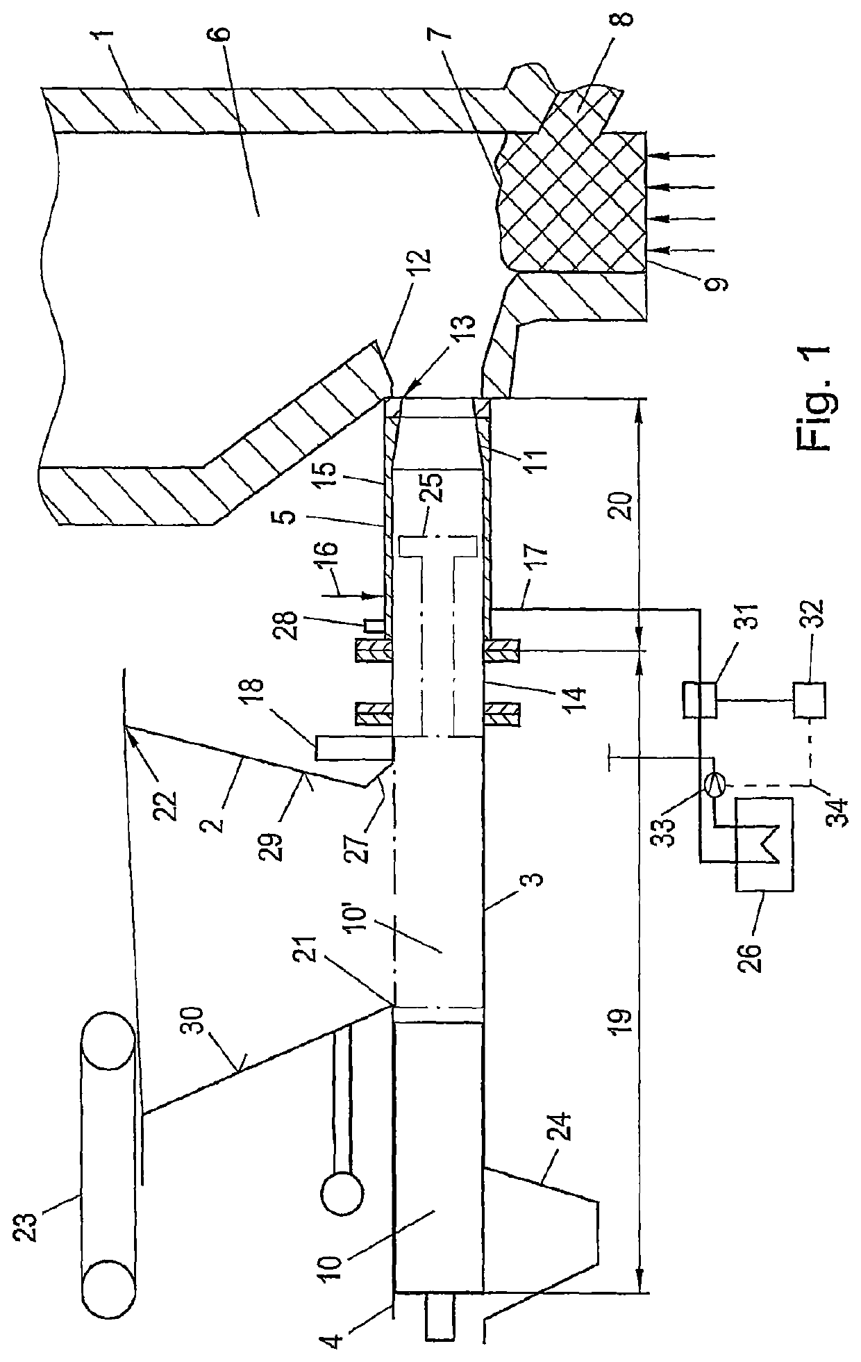
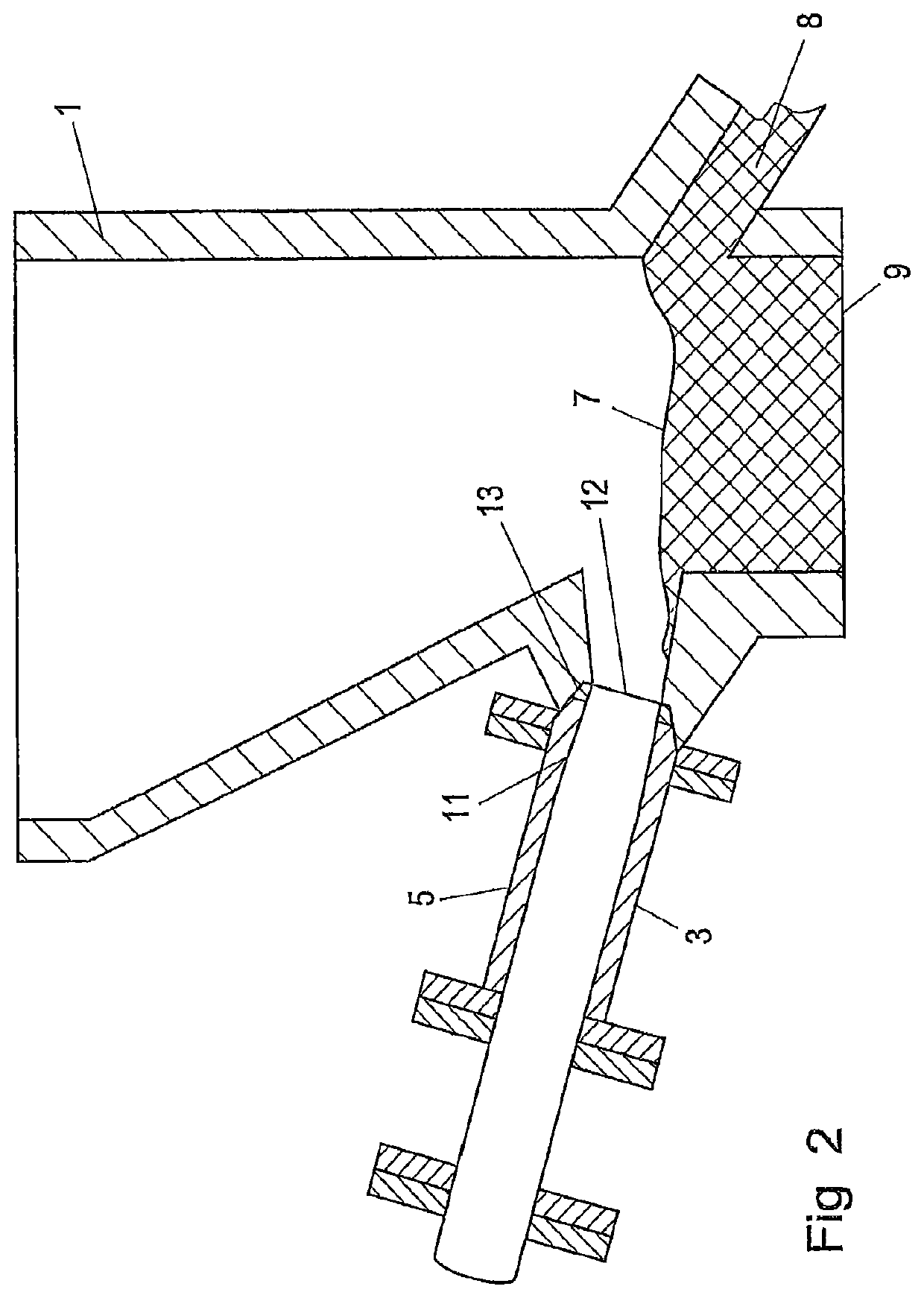
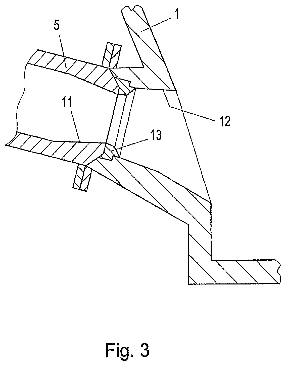
[0033]In FIG. 1, the gasification reactor 1 is in particular a reactor such as that described in AT 405937 B.

[0034]The gasification reactor 1 comprises a gasification zone 6 for accommodating a stationary bed 7 and a combustion zone (not shown in the drawing) to accommodate a fluidized bed. The gasification reactor 1 and the combustion zone (not shown in the drawing) are interconnected in the lower region via a sluice-like apparatus 8, wherein the gasification zone comprises a gas exhaust (not shown in the drawing) and a nozzle bottom 9, in particular for the injection of steam or CO2.

[0035]The mechanical conveying device 4 comprises a hydraulically drivable plunger 10 displaceably guided in a first cylindrical section 19 of the conveying pipe 3. The plunger 10 can be moved to and fro between the withdrawn position shown in the drawing with numeral 10 and the forward position shown with numeral 10′. Furthermore, the second axial section 20 of the conveying pipe 3 comprises an intern...


PUM

PropertyMeasurementUnit
temperatureaaaaaaaaaa
temperaturesaaaaaaaaaa
temperatureaaaaaaaaaa

Abstract

A method of conveying fuel, such as bulk material, into a gasification reactor that has a lateral infeed opening can be practiced with device for conveying fuels into a gasification reactor comprising a bulk material container, a conveying pipe, into which a discharge of the bulk material container opens and which can be connected to a lateral infeed opening of the gasification reactor, and a mechanical conveying apparatus disposed in the conveying pipe, the conveying apparatus is formed by a hydraulically drivable plunger, which is movably guided in a first, cylindrical section of the conveying pipe, and in that the conveying pipe has an internal cross-section which decreases continuously in the conveying direction of the fuel in order to form a compacting cone in a second axial section that is downstream of the first section, wherein the second section is configured as an exchangeable pipe portion with another exchangeable pipe portion.

Description

CROSS REFERENCE TO RELATED APPLICATIONS[0001]This Application is a divisional application of U.S. application Ser. No. 14 / 647,704, filed May 27, 2015, which is U.S. National Stage Application filed under 35 U.S.C. § 371 of International Application PCT / IB2013 / 002678, filed Nov. 29, 2013, designating the United States, which claims priority from European Patent Application 12450051.3, filed Nov. 29, 2012, and the complete disclosures of which prior applications prior applications are hereby incorporated herein by reference in their entirety for all purposes.FIELD OF THE INVENTIONS[0002]The invention relates to a device for conveying fuels into a gasification reactor, comprising a bulk material container, a conveying pipe into which a discharge of the bulk material container opens and which can be connected to a lateral infeed opening of the gasification reactor, and a mechanical conveying apparatus disposed in the conveying pipe.[0003]The invention also relates to a gasification devi...

Claims


Application Information

Patent Timeline
Patent Type & Authority Patents(United States)
IPC IPC(8): C10J3/30F23K3/12B65G53/08B65G25/08
CPCF23K3/12B65G25/08C10J3/30B65G53/08F23G2205/10C10J2200/154C10J2200/156
Inventor RENSING, MICHAEL
Owner CARE BETVERWALTUNG
Why Eureka
Try Eureka