Process for cracking hydrocarbon stream using flue gas from gas turbine

a hydrocarbon stream and flue gas technology, which is applied in the field of hydrocarbon stream cracking using flue gas from a gas turbine, can solve the problems of high flame temperature and formation of undesired nox after, and achieve the effects of increasing energy efficiency, reducing the amount of nox, and energy efficien

Active Publication Date: 2020-07-07
SABIC GLOBAL TECH BV
View PDF8 Cites 0 Cited by
  • Summary
  • Abstract
  • Description
  • Claims
  • Application Information

AI Technical Summary

Benefits of technology

[0008]It is an object of the invention to provide a process for cracking a hydrocarbon stream using a flue gas from a gas turbine which is energy efficient and in which the amount of NOx is reduced. It is also an object of the invention to provide a method for increasing the energy efficiency that saves fuel burned by the furnace of a steam cracker unit, rather than increasing the steam production by the furnace.SUMMARY OF THE INVENTION
[0019]The process of the present invention can “comprise,”“consist essentially of,” or “consist of” particular ingredients, components, compositions, steps etc., disclosed throughout the specification. It is also to be understood that a description on a product / composition / process / system comprising certain components also discloses a product / composition / system consisting of these components. The product / composition / process / system consisting of these components may be advantageous e.g., in that it offers a simpler, more economical process for the preparation of the product / composition. Similarly, it is also to be understood that, for example, a description on a process comprising certain steps also discloses a process consisting of these steps. The process consisting of these steps may be advantageous in that it offers a simpler, more economical process.

Problems solved by technology

The system of WO2015128035 has a problem that the use of preheated air results in higher flame temperatures and the formation of higher amounts of undesired NOx after combustion in the flue gas.

Method used


Image

  • Process for cracking hydrocarbon stream using flue gas from gas turbine
  • Process for cracking hydrocarbon stream using flue gas from gas turbine
  • Process for cracking hydrocarbon stream using flue gas from gas turbine

Examples


examples

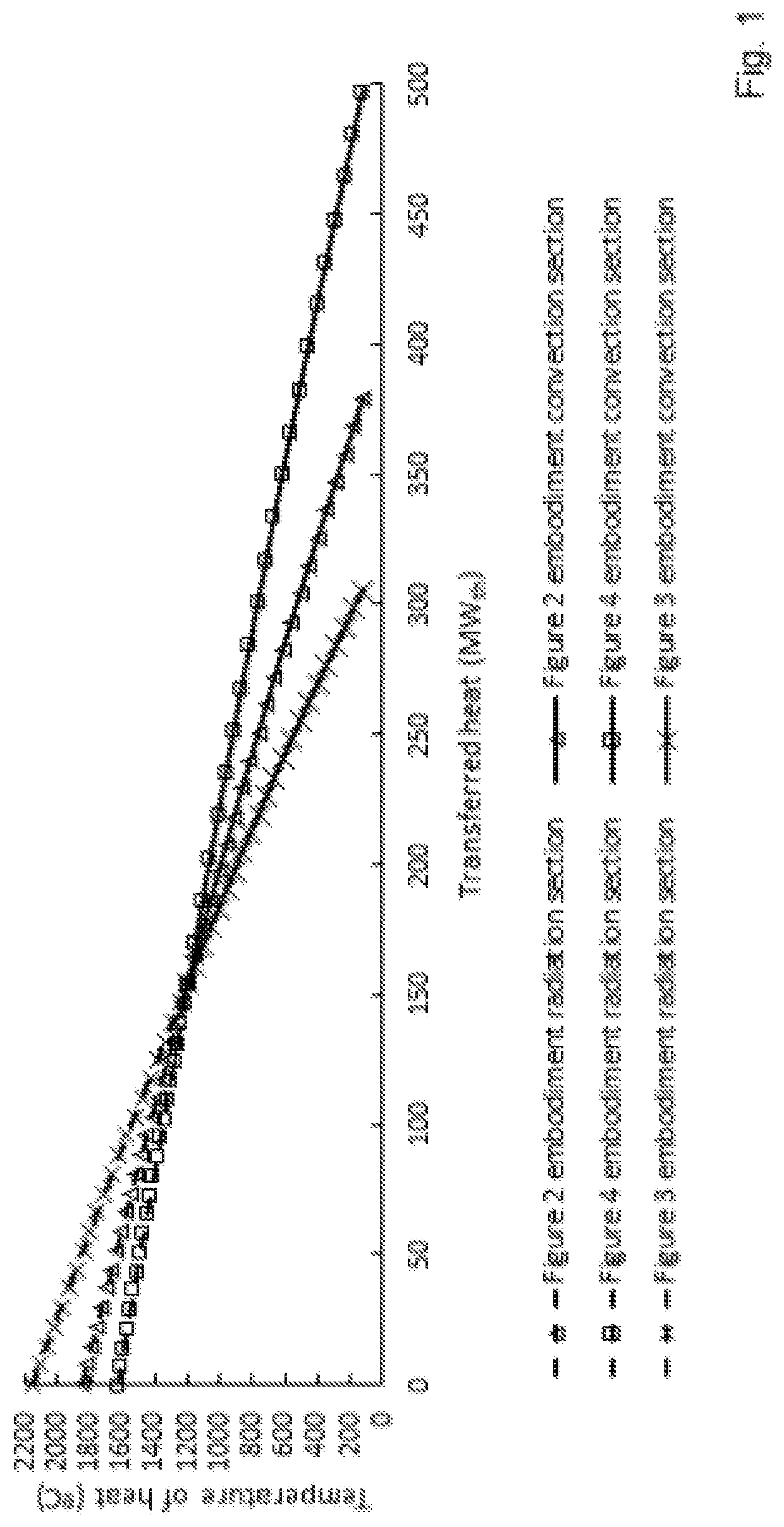
[0080]Rigorous simulations are done for a furnace steam cracking 45 t / h of hydrocarbon feedstock at a steam-to-oil ratio of 0.4. The furnace has floor and wall burners, where 80% of the heat input is provided by the floor burners and 20% by the wall burners. Ambient air temperature is 32° C. and 100% relative humidity. The simulations are performed with Pyrotec EFPS version 6 software.

[0081]Four cases are modeled:

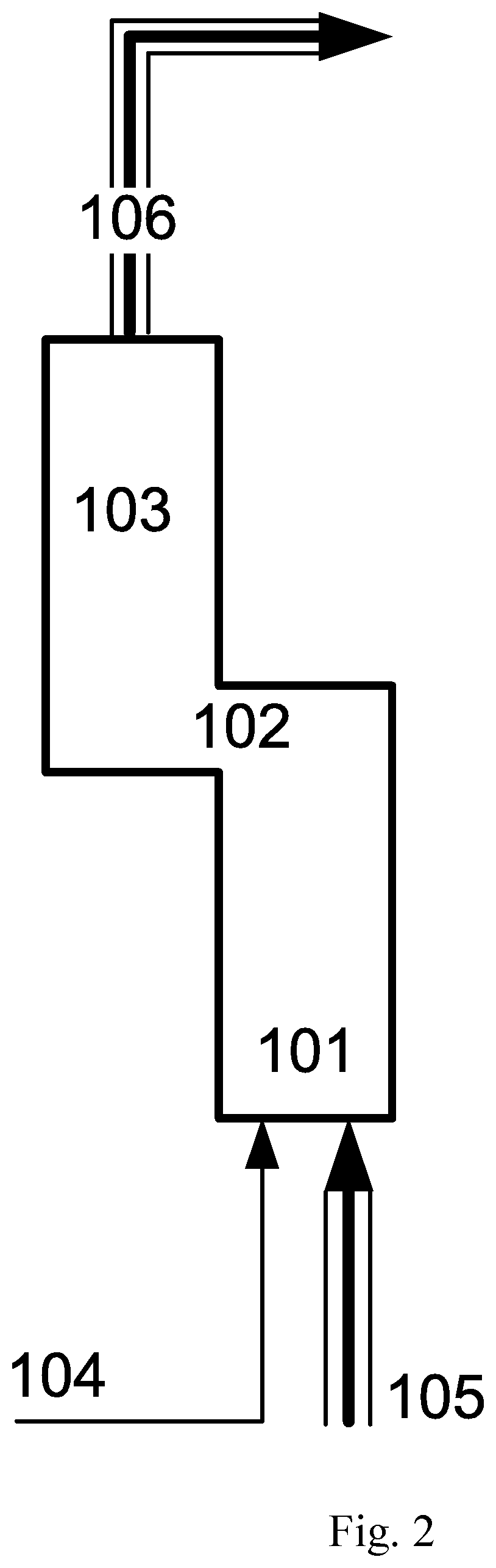
[0082]Case 0—Base case (corresponds to FIG. 2). The furnace is operated without any kind of preheated air in the design configuration at design conditions.

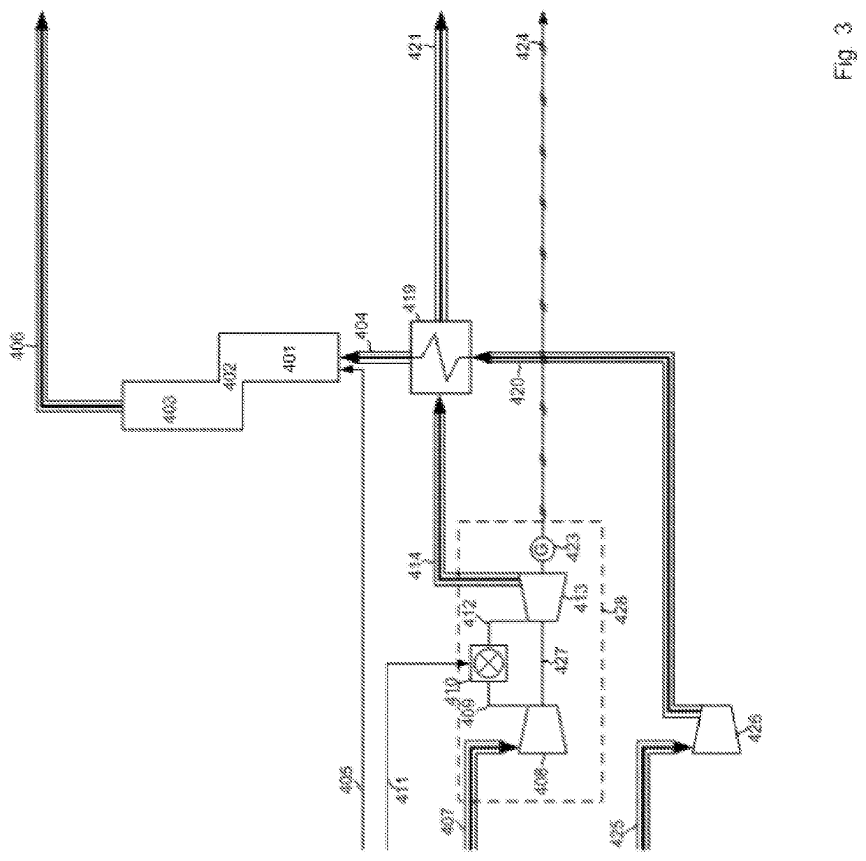
[0083]Case 1—The furnace is run with preheated air for the Floor burners only, using the system illustrated in FIG. 3. Gas Turbine exhaust gas is used to preheat ambient air to 495° C.

[0084]Case 2—The furnace is run with preheated air for the Floor burners only, using the system illustrated in FIG. 5 (according to the invention). This gas has the composition of stream 204 from table 4 and a temperature of 533° C.

[0085]Cas...


PUM

PropertyMeasurementUnit
temperatureaaaaaaaaaa
weight ratioaaaaaaaaaa

Abstract

A process for cracking a hydrocarbon stream by: combusting fuel in a gas turbine in the presence of compressed air to produce a flue gas, wherein the flue gas drives a turbine to produce electricity in a coupled generator or work to power a coupled rotating equipment; (a) feeding a first portion of the flue gas to a heat exchanger; (b) feeding ambient air to the heat exchanger to be heated by the first portion of the flue gas to provide heated air; (c) feeding a furnace with fuel and a mixture of a second portion of the flue gas and the heated air obtained by step (c) and (d) cracking the hydrocarbon stream in the furnace.

Description

CROSS-REFERENCE TO RELATED APPLICATIONS[0001]This application is a national phase under 35 U.S.C. § 371 of International Application No. PCT / M2017 / 054476, filed Jul. 24, 2017, which claims the benefit of priority of European Patent Application No. 16180943.9, filed Jul. 25, 2016, the entire contents of each of which are which ia hereby incorporated by reference in their entirety.FIELD OF THE INVENTION[0002]The present invention relates to a process for cracking a hydrocarbon stream using a flue gas from a gas turbine. In most preferred embodiments the cracking is conducted with a steam cracker.BACKGROUND OF THE INVENTION[0003]Steam cracking, also referred to as pyrolysis, has long been used to crack various hydrocarbon feedstocks into olefins, preferably light olefins such as ethylene, propylene, and butenes. Conventional steam cracking utilizes a pyrolysis furnace which has two main sections: a convection section and a radiant section. The hydrocarbon feedstock typically enters the...

Claims


Application Information

Patent Timeline
Patent Type & Authority Patents(United States)
IPC IPC(8): C10G9/36F02C3/04F02C3/00F02C6/18C10G11/00
CPCC10G9/36F02C6/18C10G11/00F02C3/00C10G2400/20F02C3/04
Inventor VAN WILLIGENBURG, JORIS
Owner SABIC GLOBAL TECH BV
Why Eureka
Try Eureka