Compressor with a thermal shield and methods of operation

a compressor and thermal shield technology, applied in the direction of liquid fuel engine components, pump components, non-positive displacement fluid engines, etc., can solve the problems of slow reduce the steady state temperature reached by the outer casing, so as to reduce or slow down the thermal transfer, reduce the steady state temperature, and slow down the heating up of the outer casing

Active Publication Date: 2020-07-14
NUOVO PIGNONE TECH SRL
View PDF24 Cites 0 Cited by
  • Summary
  • Abstract
  • Description
  • Claims
  • Application Information

AI Technical Summary

Benefits of technology

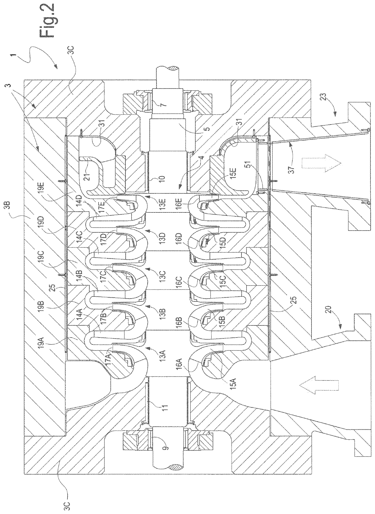
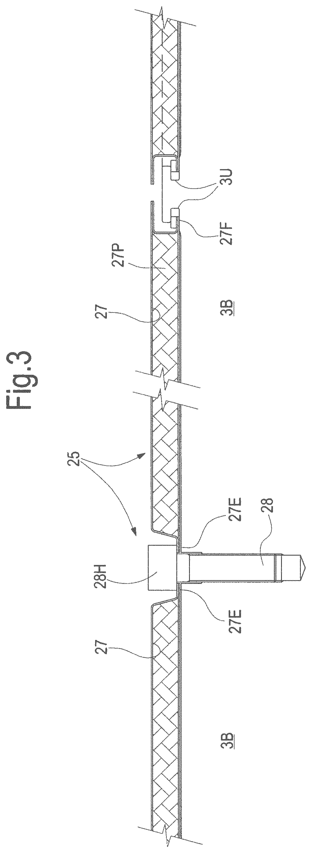
[0009]According to some embodiments, a gas compressor is provided, comprising a compressor casing and a compressor bundle arranged in the compressor casing. A thermal shield is arranged between the compressor casing and the compressor bundle. The thermal shield arrangement reduces or slows down the thermal transfer from the compressor bundle towards the compressor casing. This results in a slower heating up of the casing and also reduces the steady state temperature reached by the outer casing under continuous operating conditions of the compressor in case of natural or forced ventilation. The casing is thus subject to reduced thermo-mechanical stresses and visco-plastic deformation (or creep deformation) is prevented or retarded.
[0011]According to some embodiments the compressor can be operated for an operative time intervals, separated by cooling intervals, during which the compressor is inoperative and is allowed to cool down. The thermal shield arrangement slows the heat exchange rate between the compressor bundle and the casing, and thus increases the allowable duration of the operative time intervals.
[0014]The compressor outlet can comprise an outlet duct, forming part of the outer casing, or connected thereto. In some embodiments, an inner thermal barrier is provided between the gas passageway and the inner surface of the outlet duct. The thermal barrier limits the heat transmission from the gas flow to the gas outlet duct. The thermal barrier can comprise a thermal cladding and an inner liner, the thermal cladding being arranged between the inner surface of the outlet duct and the gas flow pathway, so that direct contact between the cladding and the gas is prevented.
[0016]Degradation of mechanical properties due to high temperature and creep damages of the outer casing are thus effectively prevented even if less performing material, such as low alloy steel, is used for the manufacturing of the outer casing.
[0019]In addition to the advantages in terms of reduction of the thermal-mechanical stress on the outer casing, the use of a thermal shield preventing or reducing the heat flow from the gas flow and the compressor bundle towards the compressor casing has the further advantage of preventing or reducing the heat dissipation from the process gas. The gas delivered by the compressor has thus an increased energy content in the form of thermal energy, which can be usefully exploited. For example, in CAES systems the higher temperature of the compressed air collected in the compressed-air container increases the overall efficiency of the system, when the air is expanded to produce mechanical power. In other embodiments, thermal energy can be extracted from the compressed gas flow and used or stored in a heat storage sink to be used in a separate process.

Problems solved by technology

This results in a slower heating up of the casing and also reduces the steady state temperature reached by the outer casing under continuous operating conditions of the compressor in case of natural or forced ventilation.

Method used


Image

  • Compressor with a thermal shield and methods of operation
  • Compressor with a thermal shield and methods of operation
  • Compressor with a thermal shield and methods of operation

Examples


Embodiment Construction

[0031]The following detailed description of the exemplary embodiments refers to the accompanying drawings. The same reference numbers in different drawings identify the same or similar elements. Additionally, the drawings are not necessarily drawn to scale. Also, the following detailed description does not limit the invention. Instead, the scope of the invention is defined by the appended claims.

[0032]Reference throughout the specification to “one embodiment” or “an embodiment” or “some embodiments” means that the particular feature, structure or characteristic described in connection with an embodiment is included in at least one embodiment of the subject matter disclosed. Thus, the appearance of the phrase “in one embodiment” or “in an embodiment” or “in some embodiments” in various places throughout the specification is not necessarily referring to the same embodiment(s). Further, the particular features, structures or characteristics may be combined in any suitable manner in one...


PUM


Abstract

A compressor includes a compressor bundle and an outer casing. Between the outer casing and the compressor bundle a thermal shield is provided, for reducing thermal stress and visco-plastic deformation of the casing under severe operating conditions.

Description

TECHNICAL FIELD[0001]The subject matter disclosed herein relates to gas compressors, in particular to multistage gas compressors, such as centrifugal multistage gas compressors.BACKGROUND[0002]Gas compressors are used in a plurality of industrial applications to boost the pressure of a gas, for example for pipeline applications, in the oil and gas industry, in carbon dioxide recovery plants, in compressed air energy storage systems and the like.[0003]The gas processed by the compressor is ingested at an inlet pressure and delivered at a higher outlet pressure, the pressure increase being obtained by conversion of mechanical power into potential pressure energy stored in the gas flow. The process provokes a temperature increase of the processed gas. In some applications the gas temperature can increase to several hundreds of degrees Celsius.[0004]Typical applications where high pressure and high temperature values are achieved by the processed gas are those relating to compressed air...

Claims


Application Information

Patent Timeline
Patent Type & Authority Patents(United States)
IPC IPC(8): F01D25/14F04D29/58
CPCF01D25/145F04D29/5853F04D29/58
Inventor GIACHETTI, SILVIOBORGHETTI, MASSIMILIANOLOMBARDI, LUCA
Owner NUOVO PIGNONE TECH SRL
Why Eureka
Try Eureka