
Actuator device based on an electroactive polymer

a polymer and electroactive technology, applied in the direction of mechanical power devices, mechanical apparatus, machines/engines, etc., can solve the problems of increasing the cost of each actuator individually with its own driver ic, affecting the operation of the device, etc., to achieve the effect of enabling the programming of the switching circuit in a short tim

Active Publication Date: 2020-07-14
KONINKLJIJKE PHILIPS NV
View PDF12 Cites 0 Cited by
  • Summary
  • Abstract
  • Description
  • Claims
  • Application Information

AI Technical Summary

Benefits of technology

[0036]This switching circuit arrangement enables a threshold voltage to be stored on the first capacitor, and this can be done each time the actuator is operated, thereby compensating for age-related changes in the threshold voltage. Thus, a low performance (i.e. instable) transistor may be used, with measurement of the threshold voltage of the current-providing TFT once per frame time to compensate for the aging effect.
[0041]In particular, the switching circuit can overcome the threshold voltage increase of amorphous silicon TFTs, whilst also enabling programming of the switching circuit in a short time.

Problems solved by technology

However, as the driving voltages of the actuators are fairly high it quickly becomes expensive to drive each actuator individually with its own driver IC.
As only (n+m) drivers are required to address up to (n×m) actuators, this is a far more cost effective approach—and also saves cost and space of additional wiring.
When a drive voltage, for example, is applied to actuate one actuator, the actuators around it also experience a voltage and will partially actuate, which is an unwanted effect for many applications.
Hence, with a passive matrix addressing scheme it is not straightforward to individually address each actuator independently of the others.
When designing an active matrix design for a field driven EAP, a problem arises that the switching device, for example transistor, needs to be able to withstand high actuation voltages, which may be hundreds of volts.
Strain in the cathode area leads to stress in the rest of the polymer matrix resulting in bending towards the anode.
In some cases, thin film electrodes are added when the polymer itself lacks sufficient conductivity.
These, as well as other low cost and low voltage technologies, typically have poorer stability, for example they suffer threshold voltage drift, which makes their usage difficult, and presents problems for the design of the driving circuitry.

Method used


Image

  • Actuator device based on an electroactive polymer
  • Actuator device based on an electroactive polymer
  • Actuator device based on an electroactive polymer

Examples


Embodiment Construction

[0070]The invention provides an actuator device which comprises an active matrix array of rows and columns of electroactive polymer actuators, each electroactive polymer actuator having a switching circuit. The switching circuit has a drive transistor and a capacitor arrangement. The capacitor arrangement is charged to a voltage derived from a drive voltage for the electroactive polymer actuator combined with a voltage derived from the drive transistor threshold voltage. During this programming of the capacitor arrangement, the EAP actuator is isolated from any current flowing. The switching circuit enables compensation for age-related changes in the threshold voltage. Thus, a low performance (i.e. with poor threshold voltage stability) transistor may be used, with measurement of the threshold voltage of the current-providing TFT once per frame time (or once per multiple frame times) to compensate for the aging effect.

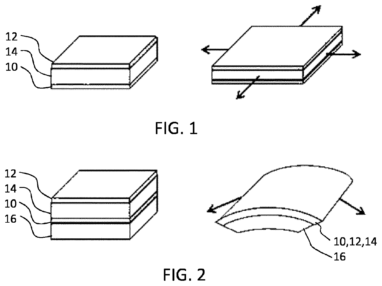
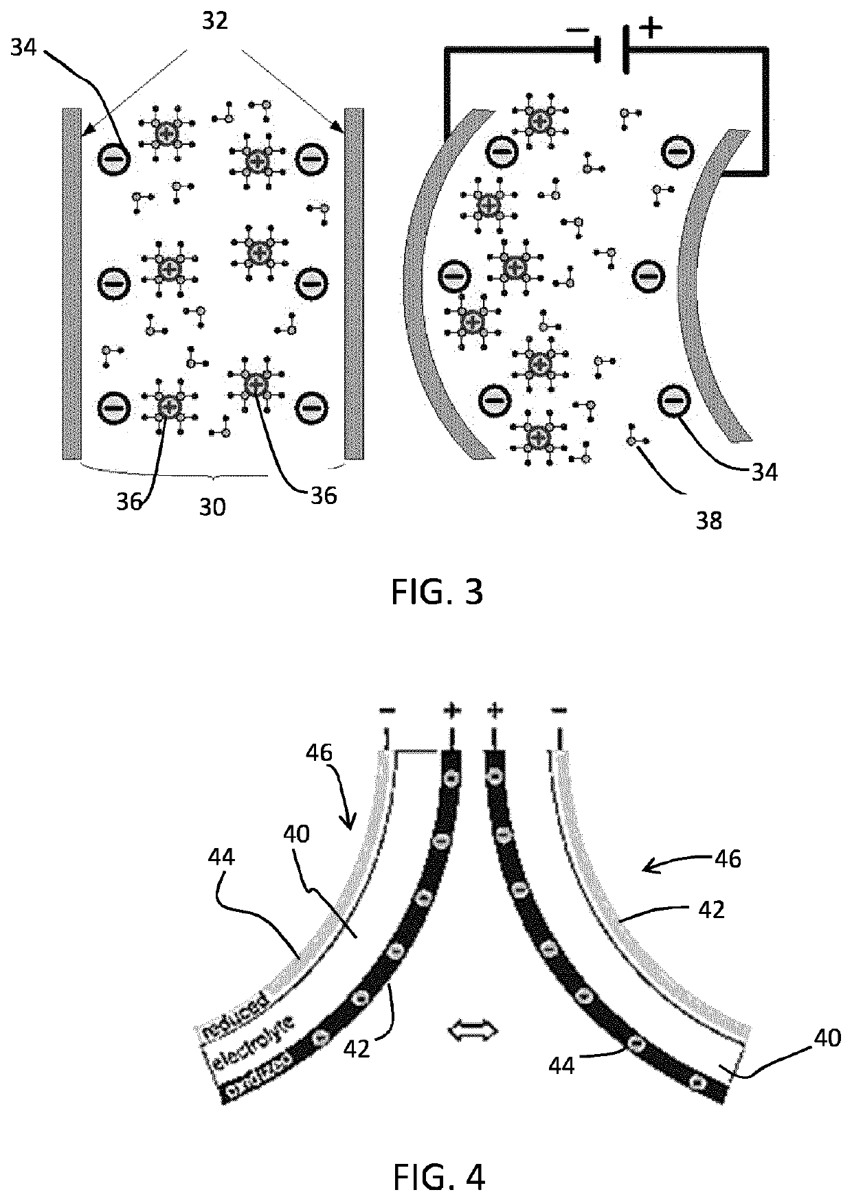
[0071]FIGS. 1 to 5 have been described in the introduction of thi...


PUM

PropertyMeasurementUnit
voltagesaaaaaaaaaa
voltagesaaaaaaaaaa
currentsaaaaaaaaaa

Abstract

An actuator device comprises an active matrix array of rows and columns of electroactive polymer actuators, each electroactive polymer actuator having a switching circuit. The switching circuit has a drive transistor and a capacitor arrangement. The capacitor arrangement is charged to a voltage derived from a drive voltage for the electroactive polymer actuator combined with a voltage derived from the drive transistor threshold voltage. During this programming of the capacitor arrangement, the EAP actuator is isolated from any current flowing. The switching circuit enables compensation for age-related changes in the threshold voltage. Thus, a low performance (i.e. with poor threshold voltage stability) transistor may be used, with measurement of the threshold voltage of the current-providing TFT once per frame time (or once per multiple frame times) to compensate for the aging effect.

Description

FIELD OF THE INVENTION[0001]This invention relates to actuator devices which make use of electroactive polymers.BACKGROUND OF THE INVENTION[0002]Electroactive polymers (EAP) are an emerging class of materials within the field of electrically responsive materials. EAP's can work as sensors or actuators and can easily be manufactured into various shapes allowing easy integration into a large variety of systems.[0003]Materials have been developed with characteristics such as actuation stress and strain which have improved significantly over the last ten years. Technology risks have been reduced to acceptable levels for product development so that EAP devices are commercially and technically becoming of increasing interest. Advantages of EAP devices include low power, small form factor, flexibility, noiseless operation, accuracy, the possibility of high resolution, fast response times, and cyclic actuation.[0004]The improved performance and particular advantages of EAP material give ris...

Claims


Application Information

Patent Timeline
Patent Type & Authority Patents(United States)
IPC IPC(8): F03G7/00
CPCF03G7/005H10N30/80H10N30/857
Inventor JOHNSON, MARK THOMASFISH, DAVID ANDREW
Owner KONINKLJIJKE PHILIPS NV
Learn More