Optical-scanning-height measuring device

a measurement device and optical scanning technology, applied in the field of optical scanningheight measuring devices, can solve the problems of difficult placement of measurement objects, inability to efficiently measure portions, and inability to easily identify desired portions of measurement objects, so as to efficiently measure the shape of a desired portion, accurate and easy inspection of second measurement objects

Active Publication Date: 2020-08-11
KEYENCE
View PDF13 Cites 1 Cited by
  • Summary
  • Abstract
  • Description
  • Claims
  • Application Information

AI Technical Summary

Benefits of technology

[0007]An object of the present invention is to provide an optical-scanning-height measuring device capable of efficiently measuring a shape of a desired portion of a measurement object.
[0032]According to the present invention, it is possible to efficiently measure a shape of a desired portion of a measurement object.

Problems solved by technology

However, it is troublesome to place the measurement object while accurately maintaining the position and the posture.
Therefore, the desired portion of the measurement object cannot be easily designated.
The portion cannot be efficiently measured.

Method used


Image

  • Optical-scanning-height measuring device
  • Optical-scanning-height measuring device
  • Optical-scanning-height measuring device

Examples


first modification

(13) First modification

[0248]FIG. 35 is a block diagram showing the control system 410 of the optical-scanning-height measuring device 400 according to a first modification. Concerning the control system 410 shown in FIG. 35, differences from the control system 410 shown in FIG. 10 are explained. As shown in FIG. 35, in the first modification, the control system 410 further includes a geometric-element acquiring section 20 and a geometric-element calculating section 21.

[0249]In the setting mode, the geometric-element acquiring section 20 receives designation of geometric elements concerning a position of a measurement point acquired by the position-information acquiring section 2. The geometric elements concerning the position of the measurement point are various elements that can be calculated on the basis of a coordinate of a portion of the measurement object S corresponding to the measurement point. The geometric elements include, for example, flatness of a desired surface of the...

second modification

(14) Second modification

[0255]FIG. 36 is a schematic diagram showing the configuration of the optical section 230 of the optical-scanning-height measuring device 400 according to a second modification. As shown in FIG. 36, the optical section 230 further includes, for example, a guide light source 233 that emits light in a visible region. The light emitted by the guide light source 233 is referred to as guide light. The light guide section 240 further includes a half mirror 247.

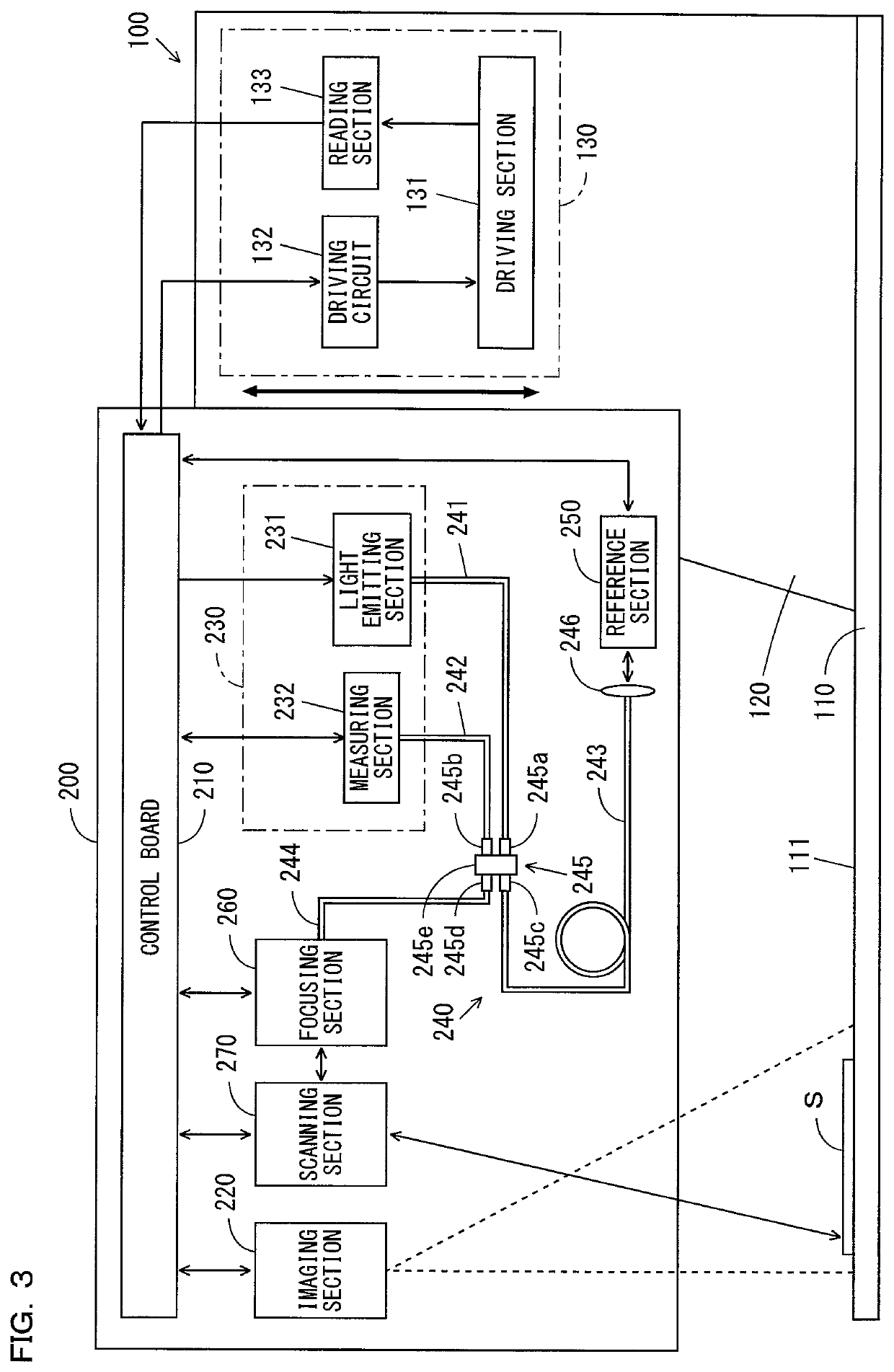
[0256]The half mirror 247 is disposed in a desired position on an optical path of measurement light output from the port 245d of the fiber coupler 245 shown in FIG. 3. The half mirror 247 superimposes the guide light emitted from the guide light source 233 and the measurement light output from the port 245d one on top of the other. Consequently, the guide light is scanned by the scanning section 270 shown in FIG. 3 and irradiated on the measurement object S in a state in which the guide light is superimposed ...


PUM

PropertyMeasurementUnit
opticalaaaaaaaaaa
height calculatingaaaaaaaaaa
heightaaaaaaaaaa

Abstract

To provide an optical-scanning-height measuring device capable of efficiently measuring a shape of a desired portion of a measurement object. Designation of a measurement point on an image of a measurement object S is received. Light emitted from a light emitting section 231 is deflected by the deflecting section and irradiated on the measurement object S. The deflecting section is controlled to irradiate the light on a portion of the measurement object S corresponding to the measurement point. A deflecting direction of the deflecting section or an irradiation position of the light deflected by the deflecting section is detected. Height of the portion of the measurement object S corresponding to the measurement point is calculated on the basis of the deflecting direction of the deflecting section or the irradiation position of the light deflected by the deflecting section and the light reception signal output by the light receiving section.

Description

CROSS-REFERENCE TO RELATED APPLICATIONS[0001]The present application claims foreign priority based on Japanese Patent Application No. 2016-256610, filed Dec. 28, 2016, the contents of which is incorporated herein by reference.BACKGROUND OF THE INVENTION[0002]1. Field of the Invention[0003]The present invention relates to an optical-scanning-height measuring device that measures a surface shape of a measurement object.[0004]2. Description of Related Art[0005]An optical-scanning-height measuring device is used to measure a surface shape of a measurement object For example, in a dimension measuring device described in JP-A-2010-43954, light irradiated from a white light source is divided into a measurement light beam and a reference light beam by an optical coupler. The measurement light beam is scanned by a measurement-object scanning optical system and irradiated on any measurement point on the surface of a measurement object. The reference light beam is irradiated on a reference-lig...

Claims


Application Information

Patent Timeline
Patent Type & Authority Patents(United States)
IPC IPC(8): G02B26/12G01B11/00G06T7/521G02B27/00G01B11/06G01N21/95G01N21/88G02B26/10G02B21/00
CPCG02B26/101G02B26/127G01B11/0608G02B21/002G02B26/123G06T7/521G01B11/00G02B27/0031G01N21/8851G01N21/95G01N21/9515G01B11/02
Inventor HOMMA, TATSUROSUGINO, KIMIHIKOSATOYOSHI, HIROYUKI
Owner KEYENCE
Why Eureka
Try Eureka