Laser-pumped plasma light source and plasma ignition method

a technology of laser-pumped plasma and light source, which is applied in the direction of gas discharge lamps, electric discharge lamps, electrical apparatus, etc., can solve the problems of light source degradation, reduced transparency of bulb walls, and spatial and energetic stability of laser-pumped plasma light sources, and achieves reliable optical breakdown, small output power, and reliable cod ignition

Active Publication Date: 2020-09-08
OBSHCHESTVO S OGRANICHENNOJ OTVETSTVENNOSTJU RND ISAN
View PDF3 Cites 5 Cited by
  • Summary
  • Abstract
  • Description
  • Claims
  • Application Information

AI Technical Summary

Benefits of technology

[0043]Designing the light source in the proposed way allows achieving the reliable ignition of the COD by choosing the appropriate energy, duration and pulse power of the first and the second laser beams due to the following factors. A reliable optical breakdown is provided by the first laser beam. However, COD ignition using only one laser beam is unstable and problematic. One of the reasons is the difficulty of superposing the CW laser focusing area with the optical breakdown area, the size of which is normally very small and does not exceed the value of around 50 μm. Even if the focusing areas of the pulsed and CW laser beams are superosed, COD ignition using only one laser beam still remains challenging. This is due to the fact that optical breakdown generated by laser radiation has an explosiv...

Problems solved by technology

One of the challenges related to designing high-brightness laser-pumped plasma light sources, relates to producing initial plasma that provides reliable ignition of the COD.
However, the relatively cold electrodes located near the high-temperature plasma region produce disturbances of convective gas flows in the chamber and, as a result, impair spatial and energetic stability of the laser-pumped plasma light source.
Also, electrode material sputtering may result in decreased transparency of the bulb walls and, correspondingly, to the light source degradation over time.
However, the need to move the radiating plasma region complicates the light source design and operation.
Besides, it makes using the sharp focusing of the laser beam more difficult, which may limit achievement of the high brightness of the light source.
The disadvantages of an electrode-containing chamber also include the complex technology for sealing the metal/glass joint and the complex chamber shape producing a concentration of stresses which result in lower strength of the chamber when operating at high gas pressures.
Thus, using the same laser with a high output power both for plasma ignition and COD sustenance either results in reduced lifetime of the light source (when the full laser power is used for COD sustenance), or is redundant, expensive and, therefore, impr...

Method used


Image

  • Laser-pumped plasma light source and plasma ignition method
  • Laser-pumped plasma light source and plasma ignition method
  • Laser-pumped plasma light source and plasma ignition method

Examples


Embodiment Construction

[0053]This description is provided to illustrate how the invention can be implemented and in no way to demonstrate the scope of this invention.

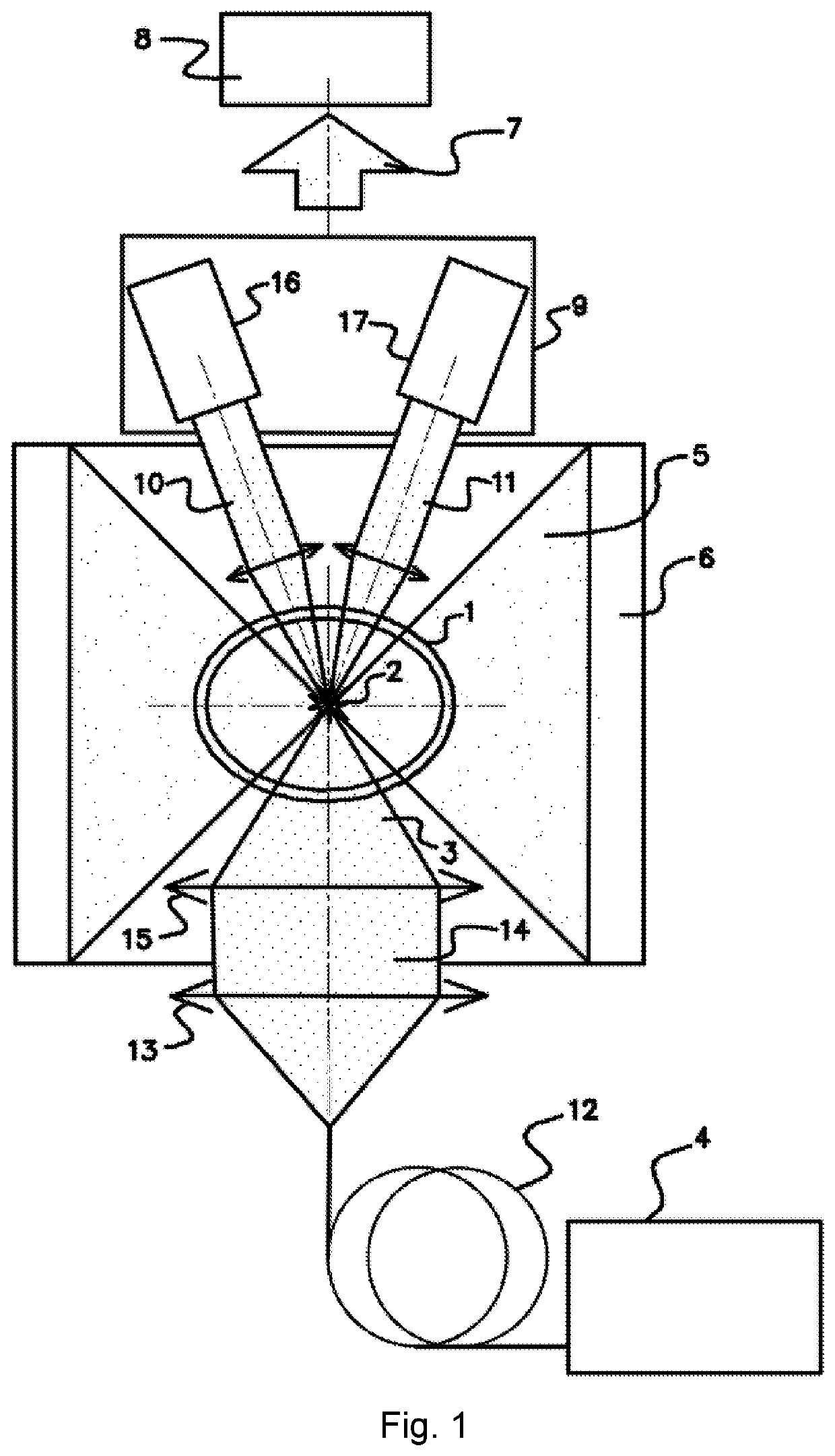
[0054]According to the example of invention embodiment shown in FIG. 1, the laser-pumped plasma light source comprises the high-pressure gas filled chamber 1, typically 10 atm or higher. At least a part of the chamber 1 is optically transparent. FIG. 1 shows an embodiment with a completely transparent chamber manufactured from an optically transparent material, e.g. fused quartz. The chamber 1 contains the radiating plasma region 2 sustained in the chamber by the focused beam 3 of the CW laser 4. At least one output beam of plasma radiation 5 directed to the optical collector 6 and intended for subsequent use, exits the chamber 1. The optical collector 6 forms the radiation beam 7 transmitted, for example, via an optical fiber and / or a system of mirrors to one or more optical consumer systems 8 which uses broadband radiation emitted by plasma...


PUM


Abstract

The light source contains a gas filled chamber with a region of radiating plasma sustained by a focused beam of a CW laser. The means for plasma ignition is a pulsed laser system generating a first and a second laser beams focused in the chamber. The first laser beam provides the optical breakdown, after which the second laser beam ignites the plasma, whose volume and density are sufficient for stationary plasma sustenance by CW laser after finishing the second laser pulse. Preferably, the first laser beam is generated in Q-switching mode and the second laser beam is generated in free-running mode. The technical result consists in ensuring high reliability of igniting the plasma, in creating in this basis electrodeless high-brightness broadband light sources with the high spatial and power stability, and in providing an ability to collect broadband plasma radiation in a spatial angle of more than 9 sr.

Description

CROSS-REFERENCE TO RELATED APPLICATIONS[0001]Current patent application claims priority to the Russian patent application RU 2020109782 filed on Mar. 5, 2020.FIELD OF INVENTION[0002]The present invention relates to electrodless laser-pumped plasma light sources producing high-brightness light in the ultra-violet (UV), visible and near infrared (NIR) spectral bands and to methods for starting plasma ignition.BACKGROUND OF INVENTION[0003]Continuous optical discharge (COD) is a stationary gas discharge sustained by laser radiation in pre-created relatively dense plasma. A COD, sustained by a focused beam of a continuous wave (CW) laser, is realized in various gases, in particular, in Xe at a high gas pressure of 10-200 atm (Carlhoff et al., “Continuous Optical Discharges at Very High Pressure,” Physica 103C, 1981, pp. 439-447). Due to a high plasma temperature of about 20,000 K (Raizer, “Optical Discharges,” Sov. Phys. Usp. 23 (11), November 1980, pp. 789-806) COD-based light sources a...

Claims


Application Information

Patent Timeline
IPC IPC(8): H01J61/54H01J61/30H01J61/02
CPCH01J61/30H01J61/541H01J61/025H01J61/54H01J65/04
Inventor ABRAMENKO, DMITRY BORISOVICHGAYASOV, ROBERT RAFILEVICHKIRYUKHIN, YURII BORISOVICHKRIVTSUN, VLADIMIR MIKHAILOVICHLASH, ALEKSANDR ANDREEVICH
Owner OBSHCHESTVO S OGRANICHENNOJ OTVETSTVENNOSTJU RND ISAN
Why Eureka
Try Eureka