Digital watermarking and signal encoding with activable compositions

a digital watermarking and signal encoding technology, applied in the field ofsignal communication, can solve the problems of limiting the ability to find and read code, increasing the cost of scanners, slowing down code reading, etc., and achieves the effect of facilitating the synchronization function of the sparse signal, facilitating detection and synchronization, and efficiently decoding signals

Active Publication Date: 2020-09-22
DIGIMARC CORP
View PDF235 Cites 9 Cited by
  • Summary
  • Abstract
  • Description
  • Claims
  • Application Information

AI Technical Summary

Benefits of technology

[0017]Sparse signaling is particularly challenging in that the sparse nature of the signal provides less opportunity to include signal for payload and robustness. In particular, there is less opportunity to include payload and synchronization. The strategy for synchronization may rely on an explicit synchronization component or an implicit synchronization component. In the latter case, the encoding of the payload may be arranged in a manner that provides a pattern that facilitates detection and synchronization.
[0018]Another important consideration for some applications is compatibility and inter-operability with other messaging protocols. For example, in the case of applying identification over the surface of objects, the signal encoding and decoding strategy should preferably support various protocols to deal with various image types, printing technologies, and scanner technologies. This design consideration dictates that sparse signaling should be compatible with encoding and decoding other signaling, like legacy encoding schemes on older objects and dense wat...

Problems solved by technology

Nevertheless, placing the code at a dedicated location limits the ability to find and read the code.
This placement of the code tends to slow down code reading or increase scanner cost by requiring additional components to capture multiple views of an object.
It also increases risk of injury due to the need for workers to re-position the object to scan the code for auto-identification.
Obviously, this undermines the theoretical speed and reliability advantages of auto-identification.
This is a challenging metric, as it has a significant subjective component.
The sparse signal has minimal impact on visual quality due to its sparse arrangement.
However, the trade-off for applications like automatic object identification is that more sophistication is required in the data signaling methodology to ensure that the data carried within the sparse signal may be reliably and efficiently recovered in many different and challenging environments.
These include computational efficiency, power consumption, memory consumption, memory bandwidth, use of networ...

Method used


Image

  • Digital watermarking and signal encoding with activable compositions
  • Digital watermarking and signal encoding with activable compositions
  • Digital watermarking and signal encoding with activable compositions

Examples


Embodiment Construction

Signal Encoder and Decoder

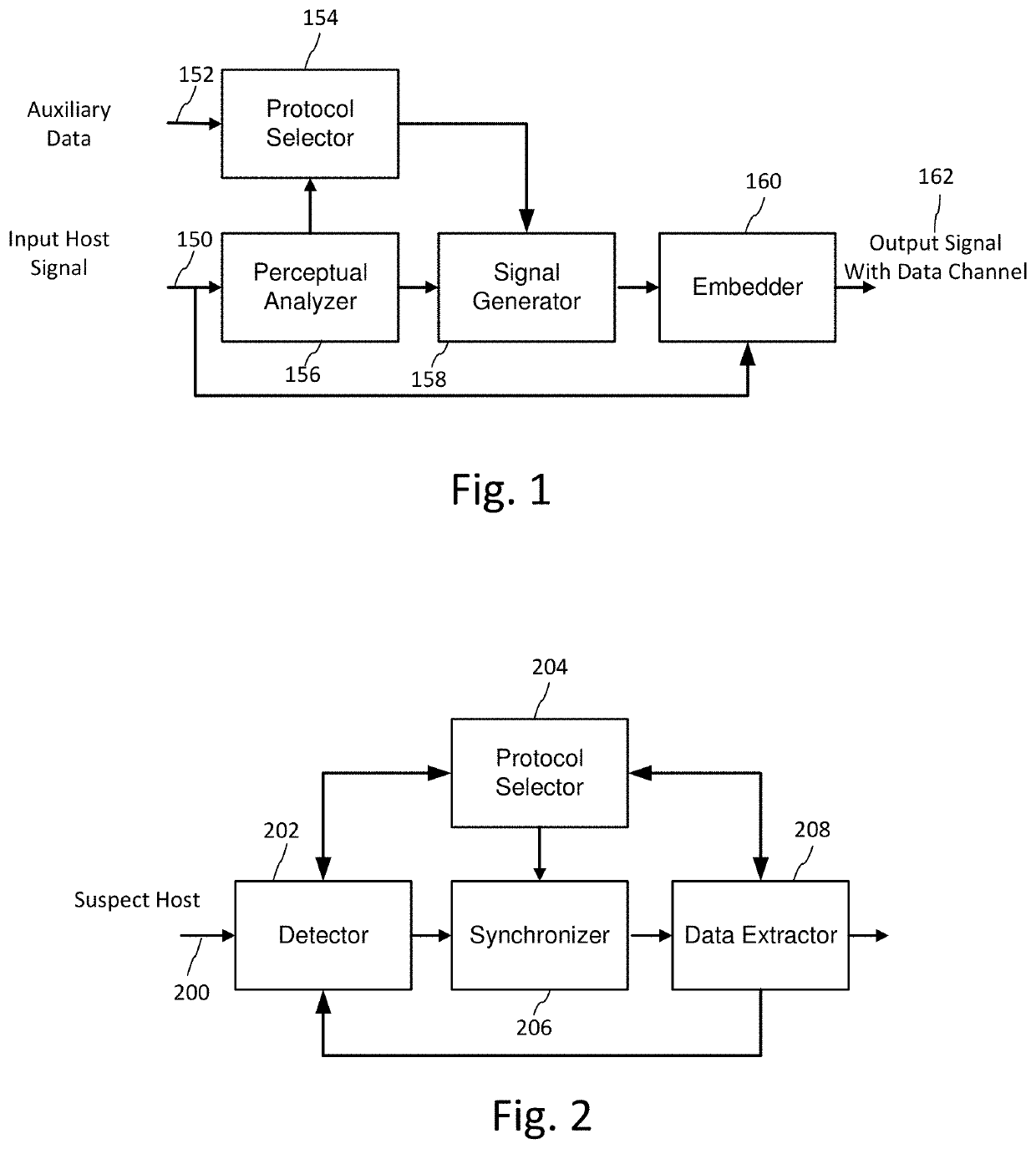
[0057]FIG. 1 is a block diagram of a signal encoder for encoding a sparse signal. FIG. 2 is a block diagram of a compatible signal decoder for extracting a payload from a sparse signal encoded on an object or within an image displayed on a video display.

[0058]Encoding and decoding is typically applied digitally, yet the signal is expected to survive digital to analog transformation and analog to digital transformation. For example, the encoder generates an image including the sparse signal that is converted to a rendered form, such as a printed image, displayed image or video. We use the term “printing” to encompass a wide variety of marking technologies, including engraving, etching, stamping, etc. as there are a variety of ways to impart the image carrying the sparse signal to an object. Prior to decoding, a receiving device captures an image or stream of images of the object through its image sensor such as a camera (e.g., CMOS or CCD), and converts it t...


PUM

PropertyMeasurementUnit
Wavelengthaaaaaaaaaa

Abstract

The present disclosure relates to signal processing such as digital watermarking and other encoded signals. One claim recites a method of offsetting color casting for a printed object associated with a retail product. The method includes: providing a first additive that absorbs light energy at or around a center wavelength of an illumination source; providing a second additive that absorbs in the ultra-violet spectrum, yet fluoresces at or around the center wavelength of the illumination source, wherein a combination of spectral responses of the first additive and the second additive offset color casting; printing the first additive, second additive and a color on the printed object, wherein the printing conveys an encoded plural bit signal. Of course, other claims and combinations are provided in the specification with reference to specific implementations and related examples.

Description

RELATED APPLICATION DATA[0001]This application claims benefit of US Provisional Patent Application No. 62 / 505,771, filed May 12, 2017. This application is also a continuation in part of U.S. patent application Ser. No. 15 / 669,103, filed Aug. 4, 2017 (issued as U.S. Pat. No. 10,304,151; published as US 2018-0130169 A1), which is a continuation of U.S. patent application Ser. No. 15 / 073,483, filed Mar. 17, 2016 (issued as U.S. Pat. No. 9,754,341), which claims the benefit of U.S. Provisional Patent Application Nos. 62 / 263,369, filed Dec. 4, 2015, 62 / 255,181, filed Nov. 13, 2015, 62 / 208,493, filed Aug. 21, 2015, 62 / 202,723, filed Aug. 7, 2015, 62 / 142,399, filed Apr. 2, 2015, and 62 / 136,146, filed Mar. 20, 2015. Each of the above patent documents is hereby incorporated herein by reference in its entirety.[0002]This application is also related to U.S. Pat. Nos. 9,380,186, 9,449,357, 9,565,335, and 9,635,378, and U.S. patent application Ser. No. 15 / 072,884 (issued as U.S. Pat. No. 10,424,...

Claims


Application Information

Patent Timeline
IPC IPC(8): G07D7/00G06K7/12G06K19/06G07D7/1205G06T1/00B42D25/333
CPCG06K19/06056G07D7/1205G06T1/0021G06K19/0614G07D7/0034G06K7/12B42D25/333B41M5/0023B42D25/387G06T1/0028G06T1/005G06T2201/0051G07D7/2008G07D7/205G07D7/206H04N1/32309H04N1/54H04N2201/327
Inventor RODRIGUEZ, TONY F.REED, ALASTAIR M.FALKENSTERN, KRISTYN R.
Owner DIGIMARC CORP
Why Eureka
Try Eureka