Supercharge Your Innovation With Domain-Expert AI Agents!

Hydraulic system for a transmission of a motor vehicle

a transmission and hydraulic system technology, applied in fluid pressure control, instruments, servomotors, etc., can solve the problems of reducing the tolerance of pressure control, affecting the clutch pressure control, increasing costs, etc., and achieve the effect of reducing the rotational speed of the pump

Active Publication Date: 2020-10-06
ZF FRIEDRICHSHAFEN AG
View PDF10 Cites 0 Cited by
  • Summary
  • Abstract
  • Description
  • Claims
  • Application Information

AI Technical Summary

Benefits of technology

The present invention provides a hydraulic system for vehicles that includes a primary system-pressure circuit and a secondary system-pressure circuit. The system includes two pumps that work together to ensure the proper pressure in both circuits. A system pressure valve is used to establish and prevent connections between the two pumps. The invention also includes a closed or open orifice to control the pressure in the secondary system-pressure circuit and a pump regulator to adjust the delivery rate of hydraulic fluid. Additionally, the invention includes a fourth liquid retention means to prevent pressure increase in the secondary system-pressure circuit due to leakage through the sailing-mode lubricating valve. The technical effects of the invention include improved hydraulic control and prevention of high pressures that could damage the system.

Problems solved by technology

In known solutions, according to which the primary and the secondary system-pressure circuits are supplied with oil with the aid of the second pump, the problem can occur that the primary system pressure can only be adjusted with a high pressure control tolerance via a pressure-controlled second pump, which can negatively affect the clutch pressure control.
A reduction of the pressure control tolerance can be accompanied by a correspondingly increased outlay—such as in the form of a pressure sensor—and, therefore, increasing costs.
One possible consequence thereof is that the transmission lubrication is undersupplied, which can result in permanent damage to the transmission.

Method used


Image

  • Hydraulic system for a transmission of a motor vehicle
  • Hydraulic system for a transmission of a motor vehicle

Examples


Embodiment Construction

[0031]Reference will now be made to embodiments of the invention, one or more examples of which are shown in the drawings. Each embodiment is provided by way of explanation of the invention, and not as a limitation of the invention. For example, features illustrated or described as part of one embodiment can be combined with another embodiment to yield still another embodiment. It is intended that the present invention include these and other modifications and variations to the embodiments described herein.

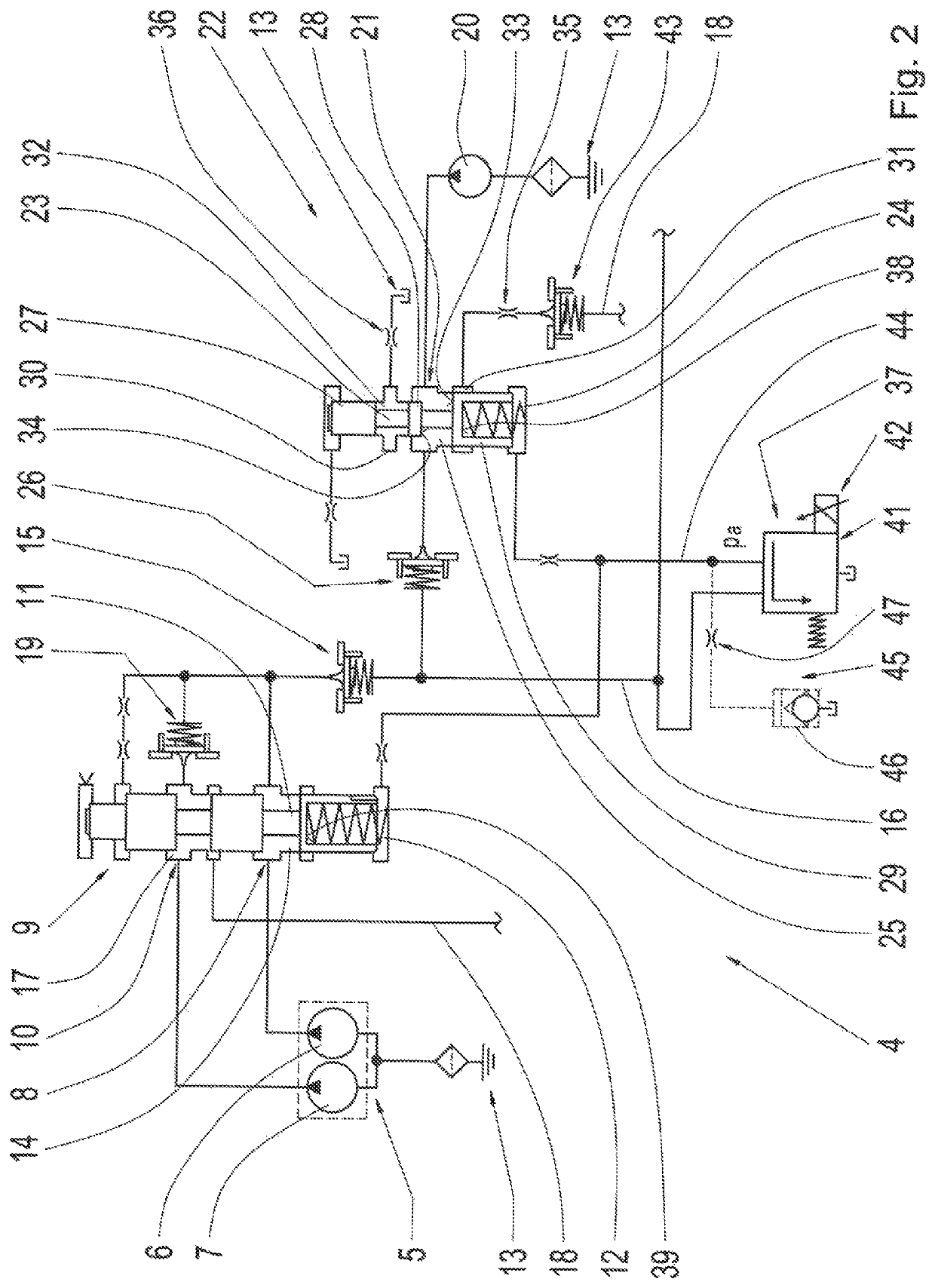
[0032]FIG. 1 shows a motor vehicle 1, specifically a passenger car in the example shown. The motor vehicle 1 includes an internal combustion engine 2 which drives the motor vehicle 1 via an automatic transmission 3 which includes a hydraulic system 4.

[0033]FIG. 2 shows one part of a circuit diagram of the hydraulic system 4 according to FIG. 1. The hydraulic system 4 includes a first pump 5, specifically a pump system in the example shown, including a primary pump 6 and a secondar...


PUM


Abstract

A hydraulic system for a transmission of a motor vehicle, the system having first and second pumps for conveying hydraulic fluid into primary and / or system-pressure circuits so that an intended pressure prevails in the circuits. The system further including liquid retention means preventing a flow of hydraulic fluid conveyed by the second pump from being conducted through the first pump when the first pump is not conveying and the second pump is conveying, and preventing a flow of hydraulic fluid conveyed by the first pump from being conducted through the second pump when the second pump is not conveying and the first pump is conveying. The system additionally including a sailing-mode lubricating valve for controlling, by an open-loop system, a flow rate of hydraulic fluid conveyed by the second pump into the primary and / or secondary system-pressure circuits such that the intended pressure is set in the system-pressure circuits.

Description

FIELD OF THE INVENTION[0001]The invention relates generally to a hydraulic system for a transmission, in particular an automatic transmission, of a motor vehicle. The hydraulic system includes a dual pump system having a first pump, which is drivable by an internal combustion engine, and an electrically drivable second pump.BACKGROUND[0002]Dual pump systems of the aforementioned type are known and utilized, in particular, in automatic transmissions of motor vehicles and in transmissions of hybrid vehicles, wherein the first and the second pumps are utilized in combination to convey hydraulic oil within the transmission at intended pressures, for example, into a primary system-pressure circuit and into a secondary system-pressure circuit. The first pump is typically a sliding vane pump which is drivable by the internal combustion engine of the motor vehicle.[0003]A sliding vane pump typically includes a stator, within which a rotor, which is eccentrically mounted with respect to the ...

Claims


Application Information

Patent Timeline
Patent Type & Authority Patents(United States)
IPC IPC(8): F16H57/04G05D16/16G05D7/06G05D16/04F15B11/17G05D7/03F16H61/00F16H59/18
CPCF16H57/0435G05D16/166F16H57/0436G05D7/0682G05D16/0404F16H61/0031G05D7/03F15B11/17F16H57/0446F15B2211/20584F15B2211/50536F16H2061/0037F16H2059/186F15B2211/6653F15B2211/20515F15B2211/20546F15B2211/526F15B2211/20523F16H61/0267
Inventor HERRMANN, MARKUSSCHMIDT, THILOHAUGG, ARMINHABERSTOCK, ALEXANDERPOPP, CHRISTIAN
Owner ZF FRIEDRICHSHAFEN AG
Features
  • R&D
  • Intellectual Property
  • Life Sciences
  • Materials
  • Tech Scout
  • Unparalleled Data Quality
  • Higher Quality Content
  • 60% Fewer Hallucinations
Learn More