Heat exchanger, heat exchange method using heat exchanger, heat transport system using heat exchanger, and heat transport method using heat transport system

a heat exchanger and heat exchange technology, which is applied in the field of heat exchangers, heat exchange methods using heat exchangers, and heat exchange methods using heat exchangers. the effect of improving the heat transfer coefficient and facilitating boiling

Active Publication Date: 2020-10-27
TOYOTA JIDOSHA KK
View PDF20 Cites 1 Cited by
  • Summary
  • Abstract
  • Description
  • Claims
  • Application Information

AI Technical Summary

Benefits of technology

[0005]JP2008-157589 A relates to a technology for facilitating boiling of a fluid, serving as a heat medium, by enabling bubbles to be easily generated based on formed grooves and irregularities on the inner surface of the pipe which is a heat transfer member.
[0025]According to the heat exchanger of the present disclosure, it is possible to control bubbles generated due to boiling, and particularly, it is possible to facilitate boiling and improve a coefficient of heat transfer from a heat source to a heat medium accordingly. Therefore, the heat transfer coefficient of the heat exchanger of the present disclosure is higher than that in the related art.
[0026]The heat transport system using the heat exchanger of the present disclosure described above can transport heat of the heat medium to other places with high efficiency.

Problems solved by technology

There are many reported examples regarding facilitating boiling as disclosed in, for example, JP2008-157589 A. However, control of the bubbles is considered to be difficult, and there has been little research on improvement of a heat transfer coefficient including control of bubbles.

Method used


Image

  • Heat exchanger, heat exchange method using heat exchanger, heat transport system using heat exchanger, and heat transport method using heat transport system
  • Heat exchanger, heat exchange method using heat exchanger, heat transport system using heat exchanger, and heat transport method using heat transport system
  • Heat exchanger, heat exchange method using heat exchanger, heat transport system using heat exchanger, and heat transport method using heat transport system

Examples


example 1

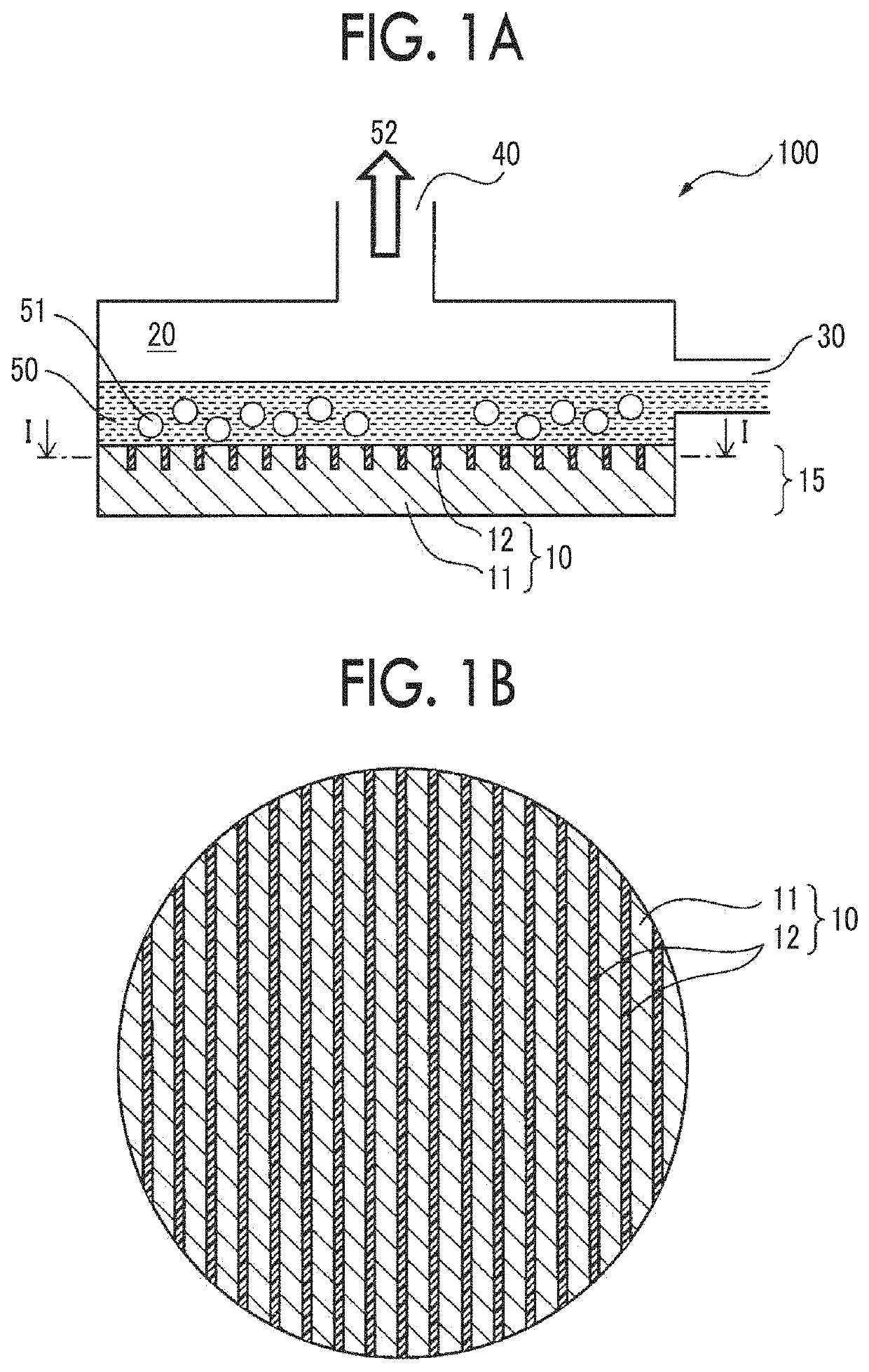
[0097]On one side surface of a copper plate having a diameter of 40 mm, grooves having a width of 0.5 mm and a depth of 0.5 mm and rectangular cross sections were formed in a form of stripes at a pitch of 2.0 mm using a milling technique.

[0098]A two-liquid curable epoxy resin was filled into the grooves formed above, curing at room temperature and post curing were sequentially performed, and a boiling surface 10 in which a copper region with a width of 1.5 mm and an epoxy resin region with a width of 0.5 mm were alternately provided in a form of stripes was formed. The thermal conductivity of the epoxy resin in the epoxy resin region was 0.1 W / mK.

[0099]A temperature of superheating ΔTsat of the boiling surface 10 was set to 30° C., a boiling experiment at a normal pressure was performed, and a heat transfer coefficient h was obtained in the same manner as in Comparative Example 1 except that the boiling surface 10 was used. The obtained heat transfer coefficient h was 0.65 as a rela...

examples 2 to 7

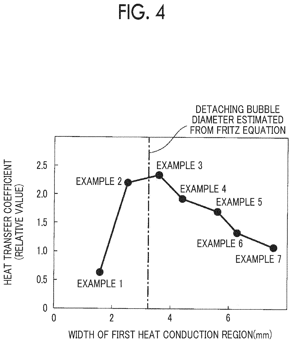
[0100]Boiling surfaces 10 having a form of stripes and a different width of a copper region were formed in the same manner as in Example 1 except that pitches of stripe grooves formed were changed as shown in Table 1.

[0101]A temperature of superheating ΔTsat of the boiling surface 10 was set to 30° C., a boiling experiment was performed at a normal pressure, and a heat transfer coefficient h was calculated in the same manner as in Comparative Example 1 except that the boiling surfaces 10 were used. The calculation results of the obtained heat transfer coefficient h are shown below in Table 1 and FIG. 4 as relative values with respect to the heat transfer coefficient h in Comparative Example 1.

[0102]

TABLE 1Structure of boiling surfaceWidth of theWidth of thefirst heatsecond heatHeat transferconductionconductioncoefficient hPitch (mm)region (mm)region (mm)(relative value)ComparativeMirror surface1ExampleExample 12.01.50.50.65Example 23.02.50.52.24Example 34.03.50.52.35Example 45.04.50...


PUM


Abstract

A heat exchanger is configured to perform heat exchange by boiling a liquid by heat transfer from a heat source to the liquid through a heat transfer member. In the heat exchanger, a first heat conduction region and a second heat conduction region are alternately provided in a form of stripes on a surface on a side that contacts the liquid such that the liquid boils via a heat transfer member.

Description

CROSS-REFERENCE TO RELATED APPLICATIONS[0001]The disclosure of Japanese Patent Application No. 2017-033753 filed on Feb. 24, 2017 is incorporated herein by reference in its entirety.BACKGROUND1. Technical Field[0002]The present disclosure relates to a heat exchanger, a heat exchange method using the heat exchanger, a heat transport system using the heat exchanger, and a heat transport method using the heat transport system.2. Description of Background Art[0003]A heat exchanger may be configured to perform heat exchange by boiling a heat medium. There have been attempts to further increase heat transfer efficiency by forming grooves, or the like, in a heat transfer member for transferring heat from a heat source to the heat medium.[0004]For example, Japanese Unexamined Patent Application Publication No. 2008-157589 (JP2008-157589 A) mentions a pipe that has an inner surface on which a plurality of grooves is formed, and in which heat is exchanged between a fluid that flows inside the...

Claims


Application Information

Patent Timeline
Patent Type & Authority Patents(United States)
IPC IPC(8): F28F13/08F28F3/02F28F13/14F28D15/02F28F13/18F28F1/40F28F1/42
CPCF28F13/14F28F13/187F28F3/027F28D15/02F28F1/40F28F13/08F28F1/426F28F2250/10F28F13/18F28F3/046F25B23/00F28D21/0001F28F3/00F28F3/048
Inventor KUSANO, YUYAYAMASHITA, SEIJI
Owner TOYOTA JIDOSHA KK
Why Eureka
Try Eureka