Control interface for a machine-vision lighting device

a technology of lighting device and control interface, which is applied in the direction of instruments, television systems, material analysis through optical means, etc., can solve the problems of high cost and complexity of associated programming, light sources that do not provide continuous illumination, and interfaces that are however rare, and achieves simple production and small bulk

Active Publication Date: 2020-11-24
TPL VISION UK LTD
View PDF8 Cites 0 Cited by
  • Summary
  • Abstract
  • Description
  • Claims
  • Application Information

AI Technical Summary

Benefits of technology

[0012]Thus, the interface according to the invention allows external lighting to be controlled using origin light signals emitted, for example, by light sources included in the camera system, in particular when these light sources are not able to guarantee an acceptable contrast for the processing of the image. This interface is simple to produce and has a small bulk.
[0047]Again preferably, the light sensors are placed, and in particular isolated by the mask, so that the light that they receive originates, with respect to more than 50%, preferably more than 70%, preferably more than 90%, and preferably substantially 100% of the intensity thereof, from the one or more origin light sources, which are preferably integrated into the camera. Advantageously, the light captured by the light sensors is substantially not influenced by the exterior environment of the camera system. The inspection of the quality of the light emitted by the one or more automatically controlled light sources is thereby improved.
[0051]In one preferred embodiment, the mask therefore isolates not only the one or more origin light sources from the scene observed by the objective of the camera, but also isolates the one or more light sensors from the automatically controlled light sources.

Problems solved by technology

Lastly, conventionally, the light sources do not provide illumination continuously, but do so intermittently, in the manner of a stroboscope.
These interfaces are however rare because of the high cost and complexity of the associated programming, in particular when a plurality of light sources must be controlled in coordinated sequences to emit different colors and / or different light intensities.
They however have a limited reactivity that may degrade the precision of the specified turn-on sequences.
However, this integrated lighting allows only directional and monochromatic lighting to be produced, this limiting the ability to define a lighting method that is optimal for a given situation.

Method used


Image

  • Control interface for a machine-vision lighting device
  • Control interface for a machine-vision lighting device
  • Control interface for a machine-vision lighting device

Examples


Embodiment Construction

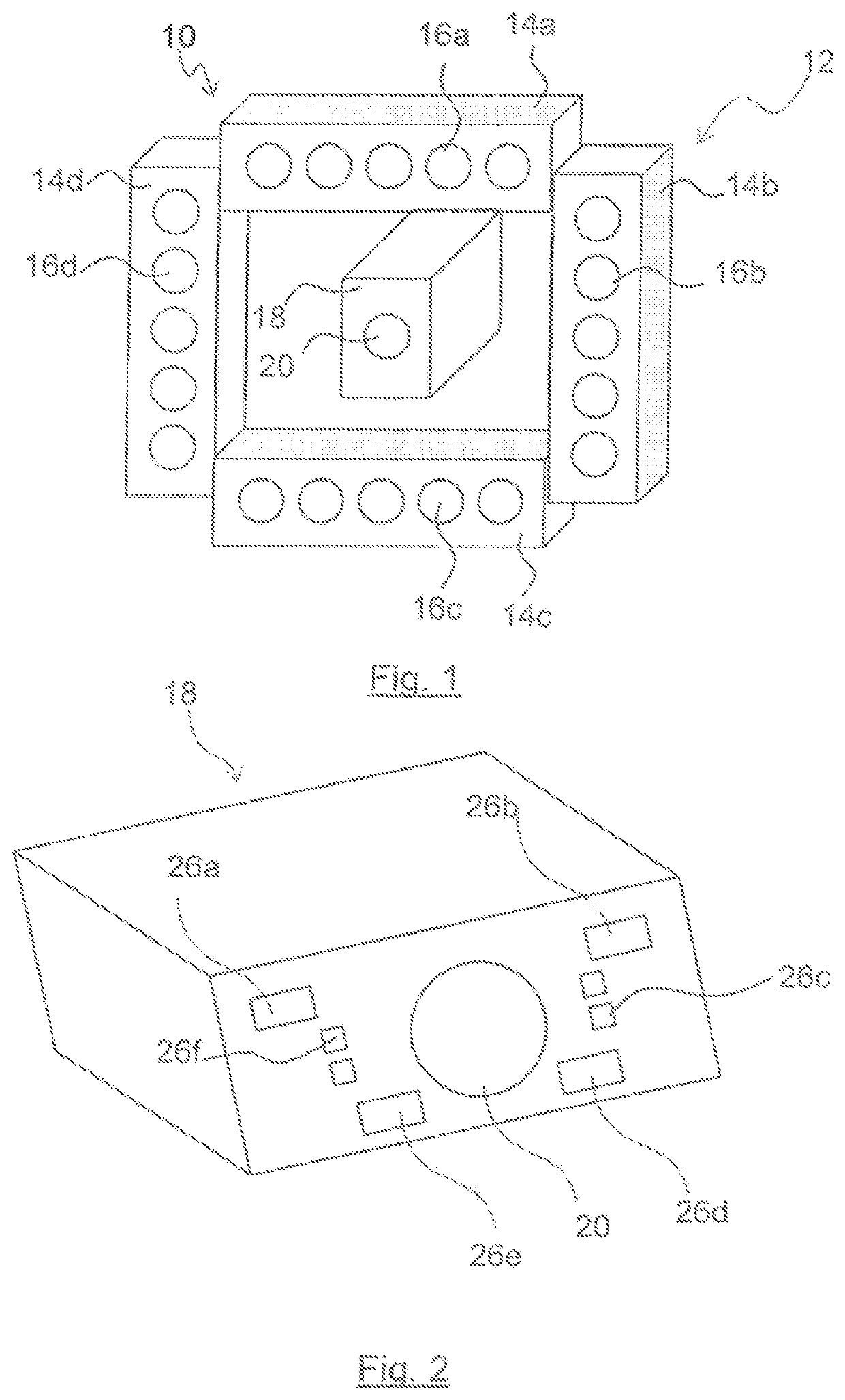
[0078]FIG. 1 shows an example of a machine-vision device 10. This device 10 comprises a lighting device 12, for illuminating a zone of interest, for example a segment of a conveyor belt. The lighting device 12 here comprises four automatically-controlled-light-source holders 14 (14a-14d) to each of which five respective automatically controlled light sources 16 (16a-16d), in the present case LEDs or groups of LEDs that operate synchronously, are fastened.

[0079]The machine-vision device 10 also comprises a camera system 18 that is independent of the lighting device 12, in order to capture an image of the zone of interest illuminated by the lighting device 12. The camera system is for example connected to a unit for processing the images captured by the camera, in order to identify items located in the illuminated zone of interest and to detect items that do not meet a defined criterion.

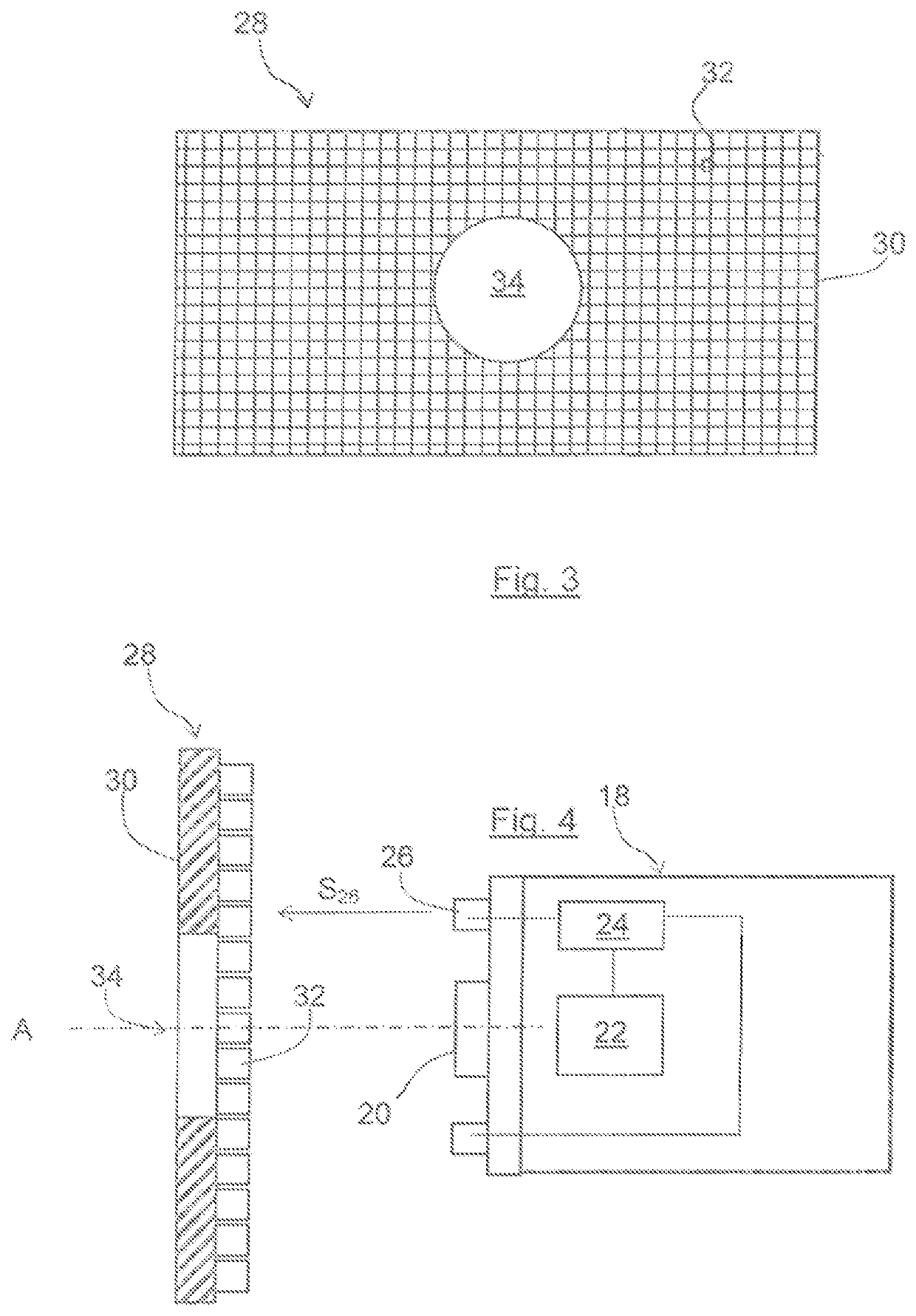
[0080]The camera system 18, which is shown in more detail in FIGS. 2 and 4, comprises an objective ...


PUM

PropertyMeasurementUnit
widthaaaaaaaaaa
radiusaaaaaaaaaa
radiusaaaaaaaaaa

Abstract

A machine-vision device including a camera system, with a camera and an integrated origin light source that is integrated into the camera system, and a lighting device with: control interface including: a plurality of light sensors each for capturing a respective origin light signal, and emitting a respective sensor signal, and an electronic unit for processing the sensor signal configured so as to transmit a respective control signal to a respective output of the processing electronic unit. The lighting device with one or more automatically controlled light sources that are external to the camera system, each connected to one respective output of the processing electronic unit by respective connection, so as to be controlled with the control signal delivered to the output. At least one light sensor is placed so as to directly capture the light emitted by one origin light source.

Description

TECHNICAL FIELD[0001]The present invention relates to a control interface for a machine-vision lighting device, to a machine-vision lighting device, to a machine-vision device and to a device for conveying items including such an interface. According to another aspect, the invention relates to a method for controlling a machine-vision lighting device.PRIOR ART[0002]In the industrial field it is known to inspect items, in particular items conveyed on a conveyor line, with respect to defects, dimensions and / or color, or indeed to read codes present on these items. This inspection is advantageously carried out automatically in order to be objective and repeatable. To do this, a machine-vision device is employed, for example with a view to sorting the items depending on the inspection carried out. For example, a mechanical arm may be used to remove, from a conveyor line, items considered to be defective. The machine-vision device includes light sources that illuminate a zone of interest...

Claims


Application Information

Patent Timeline
Patent Type & Authority Patents(United States)
IPC IPC(8): G01N21/88H05B45/00G03B15/05H04N5/232H04N5/235H05B44/00
CPCH05B45/00G03B15/05G01N21/8806H04N5/23206H04N5/2354G03B2215/0557G01N2201/063G01B11/24G03B2215/0521G03B2215/0567G03B2215/0575G01N2021/8838H05B45/22H04N23/56H04N23/74H04N23/661
Inventor MAZEAUD, GUILLAUME
Owner TPL VISION UK LTD
Why Eureka
Try Eureka