Methods and devices for diastolic assist

a diastolic assist and diastolic technology, applied in the field of diastolic assist devices, can solve the problems of limited cardiac output, abnormal diastolic part of the cardiac cycle, and insufficient blood supply in the left ventricl

Active Publication Date: 2020-12-15
CORDYNAMIX
View PDF13 Cites 1 Cited by
  • Summary
  • Abstract
  • Description
  • Claims
  • Application Information

AI Technical Summary

Benefits of technology

[0008]In a first variation, the disclosure includes a method of improving a diastolic heart function in a heart of a patient having diastolic heart dysfunction. One variation of the method includes positioning a medical device within a body of the patient; advancing the medical device into an interior chamber of the heart; creating at least one incision in cardiac muscle forming an interior heart wall of the interior chamber without cutting through the exterior part of said heart wall, where the incision is sufficient to reduce a stiffness of the interior chamber to increase volume of the chamber and reduce diastolic filling pressure.
[0010]Typically, the method includes creating at least one incision without reducing integrity of the cardiac muscle.
[0016]Another variation of the method includes a method of increasing blood flow in a diseased heart. One such example includes positioning a medical device within a body of the patient; advancing the medical device into an interior chamber of the heart; locating a target area of heart tissue; and creating at least one incision in cardiac muscle of the heart tissue to decrease the stiffness of the interior chamber to permit the interior chamber to increase in volume during diastole. One variation of the device used to make the one or more incisions mentioned above includes a soft semicircular tip at the distal end of the device that may be in fluid communication with an injection port outside the patient. The tip can be imaged when inside the heart under x-ray fluoroscopic imaging or any other type of imaging or virtual tracking. When the tip is placed into the area of the apex of the heart, the tip configuration changes and the change can be seen during imaging. A contrast imaging agent may be injected through the tip when injected outside the patient through the injection port. Said contrast agent flows into the ventricle. The pattern of flow gives information to the user as to where the cutting member is relative to the inside wall of the ventricle. When the cutting member is adjacent to or embedded in the muscle of the heart wall, the contrast agent will flow only to the surface of the inside wall while the cutting element will be seen within that wall. The contrast agent can also be seen within the cat made in the heart wall.
[0024]The devices described herein can further include a rigid section at the far end of the flexible shaft where the rigid section comprises an opening through which the cutting surface of the cutting member extends when pivoted. As discussed herein, the rigid section at the far end of the device provides uniformity to create the incision, while the flexible nature of the shaft permits navigation to remote tissues through tortuous anatomy.

Problems solved by technology

However, in patients experiencing DHF, the part of the cardiac cycle that involves diastole is abnormal as the left ventricle cannot relax or expand sufficiently.
The inability of the left ventricle to fully relax results in sub-optimal filling of the left ventricle with blood.
The abnormal filling of the ventricles in DHF results in limited cardiac output, especially during exertion.
As a result, for any given ventricular volume in a heart with DHF, ventricular pressures are elevated, with backup in the circulatory system, leading to pulmonary congestion and edema identical to those seen in patients with SHF.
This dysfunction can ultimately lead to multi-organ dysfunction and death.
There are currently no approved devices for diastolic dysfunction.
Additionally, pharmaceutical intervention has not yet shown to improve outcomes in this population.

Method used


Image

  • Methods and devices for diastolic assist
  • Methods and devices for diastolic assist
  • Methods and devices for diastolic assist

Examples


Embodiment Construction

[0038]The illustrations described herein are examples of the invention. Because of the scope of the invention, it is specifically contemplated that combinations of aspects of specific embodiments or combinations of the specific embodiments themselves are within the scope of this disclosure.

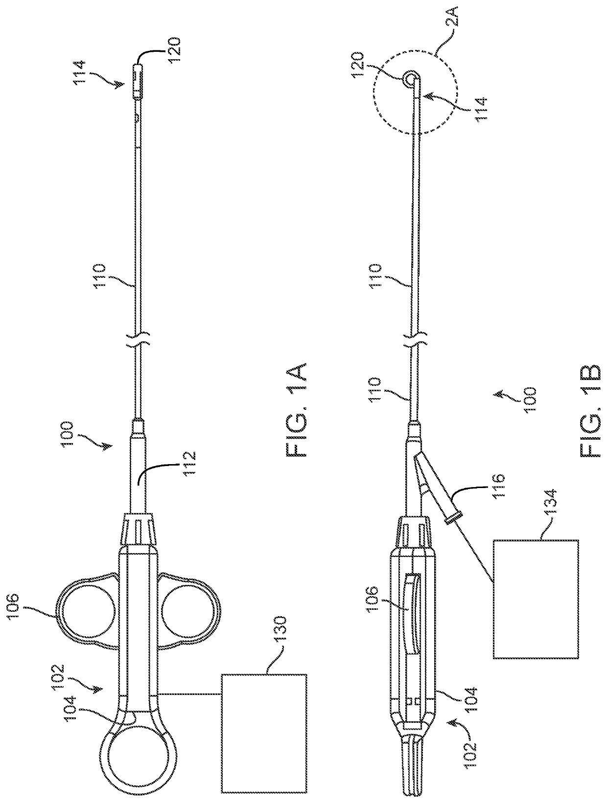
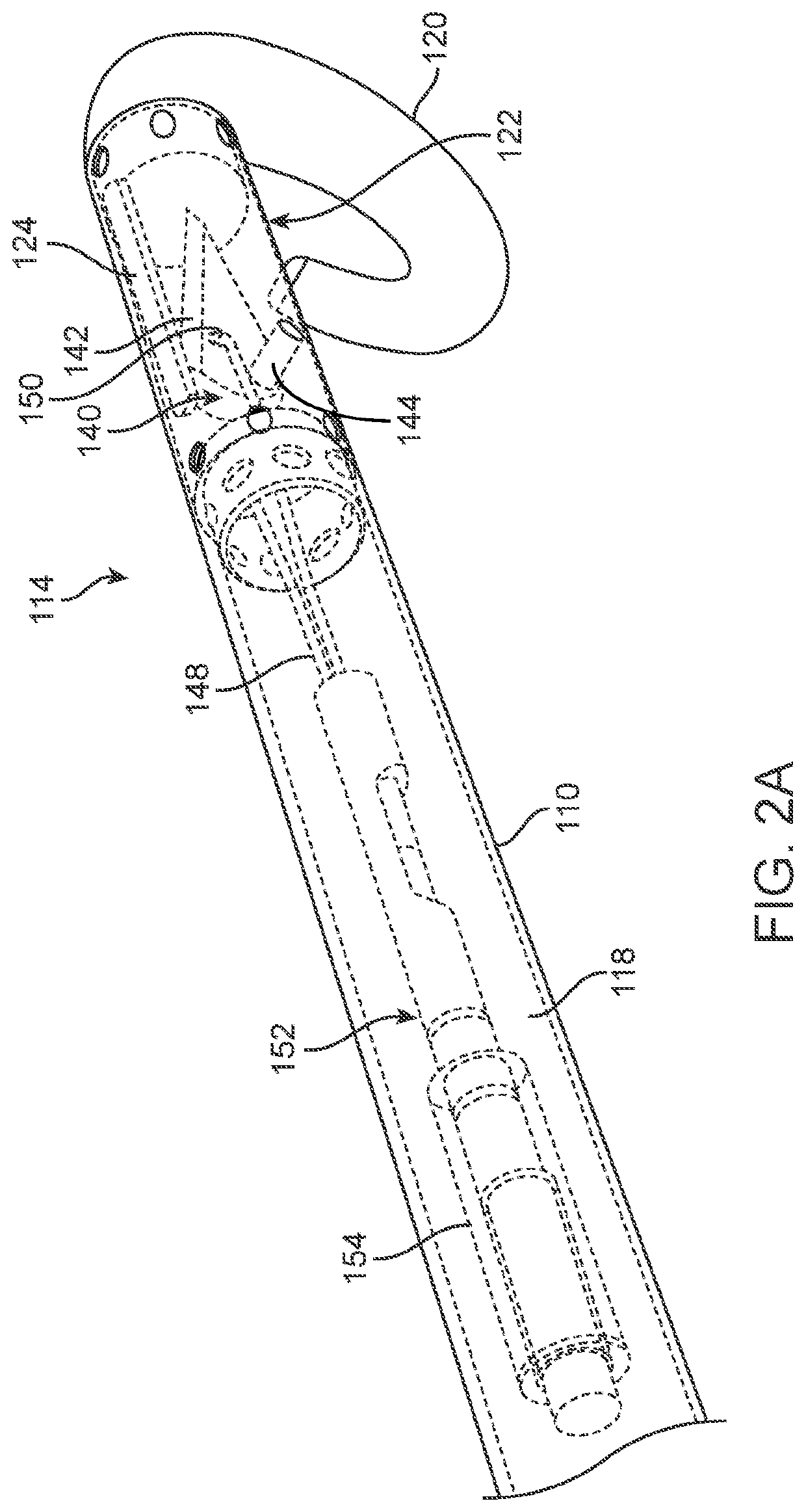
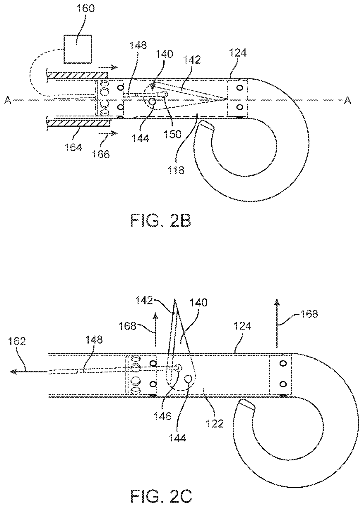
[0039]As noted above, the methods described herein increase a volume of a chamber of a heart to improve blood flow in diastolic heart failure. For example, incisions, cuts, holes, or other separation of tissue can be made in muscle forming the wall of the left ventricle to improve a diastolic function of the heart. Although the description and claims described herein discuss primarily treatments occurring in a left ventricle, unless specifically discussed or claimed, the treatments can occur in any chamber of the heart (e.g., the atriums and / or ventricles). Typically, access to the chambers of the heart (endocardium) can be made percutaneously or via a transapical approach. Once in the ventricle, ...


PUM


Abstract

The devices and method described herein allow for therapeutic damage to increase volume in these hyperdynamic hearts to allow improved physiology and ventricular filling and to reduce diastolic filling pressure by making the ventricle less stiff.

Description

CROSS-REFERENCE TO RELATED APPLICATIONS[0001]This is a non-provisional of U.S. Provisional Application 62 / 265,424 filed on Dec. 10, 2016, the entirety of which is incorporated by reference. This application also incorporates by reference: U.S. Provisional Application 61 / 911,456 filed on Dec. 3, 2013; and U.S. patent application Ser. No. 14 / 152,189 filed on Jan. 10, 2014.BACKGROUND OF THE INVENTION[0002]Congestive heart failure (CHF) in the U.S. has a prevalence of approximately 5.8 million people and an incidence of approximately 550,000 people annually. CHF is a rapidly growing medical problem, CHF can be categorized as either systolic heart failure (SHF) or diastolic heart failure (DHF). The estimated direct and indirect cost of CHF in the United States for 2009 is $37.2 billion. CHF is the primary reason for 12-15 million office visits and 6.5 million hospital days each year. CHF is also thought to be the cause of at least 20 percent of all hospital admissions among patients olde...

Claims


Application Information

Patent Timeline
Patent Type & Authority Patents(United States)
IPC IPC(8): A61B18/14A61B17/3211A61B6/12A61B6/00A61B17/32A61B90/00A61B18/00A61B17/00A61B17/22A61B17/3209A61N1/05
CPCA61B6/12A61B18/1492A61B90/39A61B17/320016A61B6/487A61B17/3211A61B90/06A61B2018/1475A61B2018/00083A61B2018/00351A61B2017/00247A61B2017/00477A61B2017/00243A61B2018/00827A61N1/056A61B2090/3966A61B2018/00892A61B2018/00589A61B2018/00172A61B2017/00044A61B2017/22071A61B2017/00862A61B2018/1412A61B2018/00904A61B17/3209A61B2018/00601A61B2018/00839A61B2018/00595A61B2018/00077A61B2090/064
Inventor LAUFER, MICHAEL D.
Owner CORDYNAMIX
Why Eureka
Try Eureka