
Wind turbine having low-harmonic converter system, and method for operation

a converter system and wind turbine technology, applied in the direction of machines/engines, dc-ac conversion without reversal, harmonic/ripple reduction through ac network, etc., can solve the problems of harmonic disturbance grid, high cost, complicated configuration, etc., and achieve the effect of reducing harmonics more selectively

Active Publication Date: 2020-12-29
SENVION GMBH
View PDF9 Cites 0 Cited by
  • Summary
  • Abstract
  • Description
  • Claims
  • Application Information

AI Technical Summary

Benefits of technology

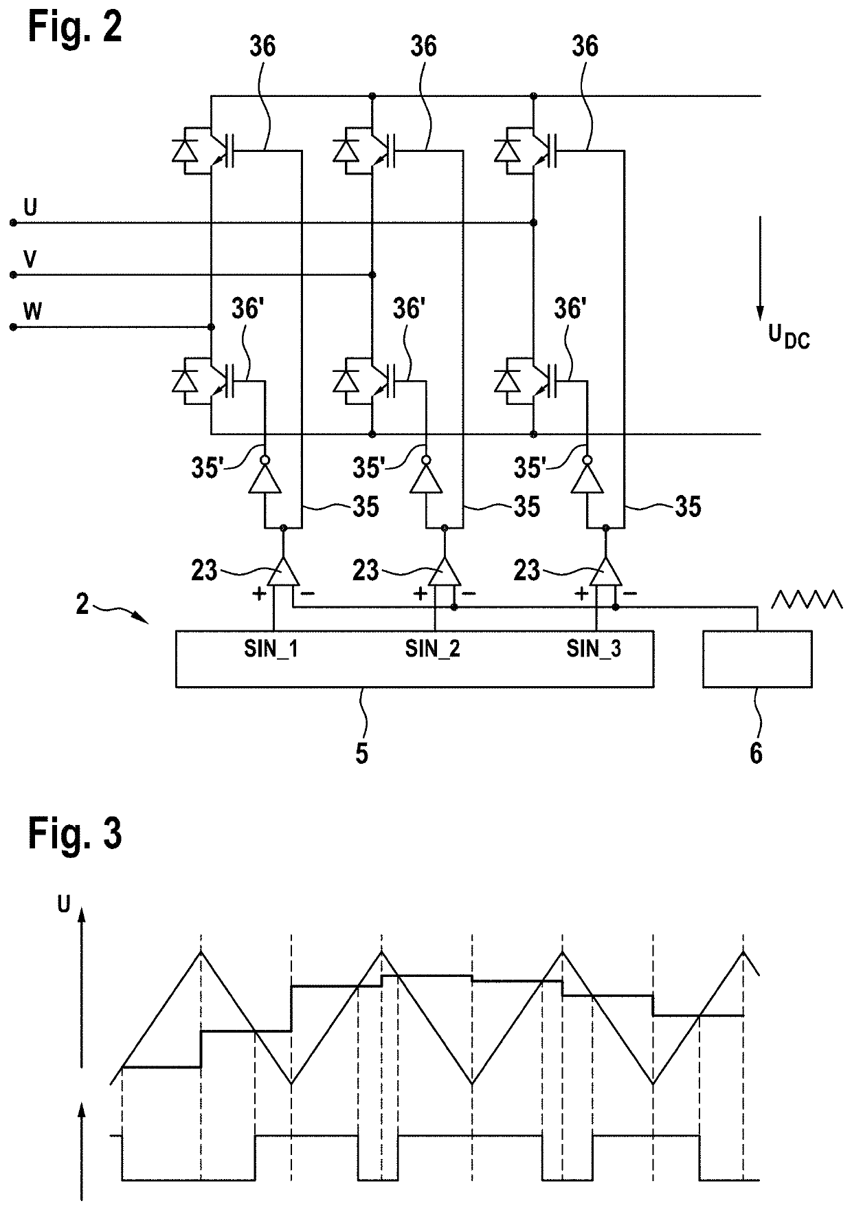
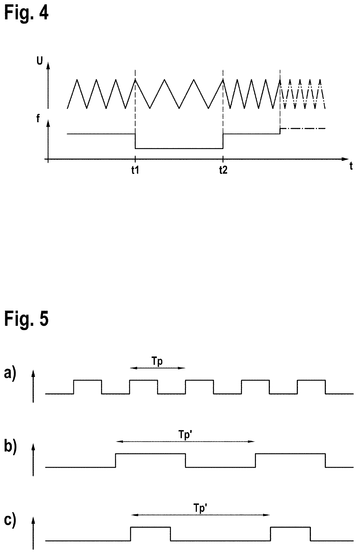
The invention is about reducing harmonics in wind turbines. The invention uses two different switching frequencies to selectively reduce harmonics. The switching frequencies are chosen in an odd-number multiples of the original frequency, which helps to avoid intermediate frequencies that can cause control system issues in the grid. The method is simple and can be easily adapted without the need for additional hardware. Switching losses are not increased and the harmonic spectrum can be influenced in a selective way. The use of a third switching frequency can further enhance the reduction of harmonics. The switchover between frequencies should be synchronized in phase with the carrier signal to avoid distortional effects.

Problems solved by technology

These harmonics disturb the grid, and are therefore unwanted.
The latter are not only very expensive, but also require elaborate configuration.
Owing to the impedance present in the grid (in particular transformer impedance and grid impedance), the voltage harmonics that are thus not fully eliminated become harmonic currents in the grid.
These harmonic currents load the grid, and are therefore unwanted.
Fulfilling the latter, particularly in the case of so-called soft grids, is extremely demanding.
The reduction of harmonics by additional L-C-L filters, known per se, is too demanding of resources for general application, and moreover is not sufficiently specific to eliminate particularly disturbing harmonics.
Moreover, the multiplication of the switching frequency can cause an adverse increase in the switchover losses.

Method used


Image

  • Wind turbine having low-harmonic converter system, and method for operation
  • Wind turbine having low-harmonic converter system, and method for operation
  • Wind turbine having low-harmonic converter system, and method for operation

Examples


Embodiment Construction

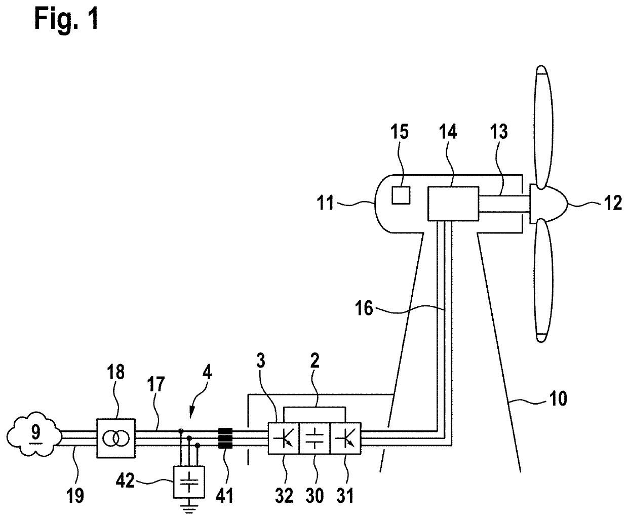
[0035]For the purpose of explaining an exemplary embodiment of the invention, reference is first made to FIG. 1. It shows a wind turbine according to an exemplary embodiment of the invention, denoted in its entirely by the reference 1, that is suitable for executing the method according to the invention.

[0036]The wind turbine 1 comprises a tower 10, arranged at the upper end of which, so as to be slewable in the azimuthal direction, is a nacelle 11. Rotatably arranged on an end face of the nacelle 11 is a wind rotor 12. It comprises a hub having one or more rotor blades and, via a rotor shaft 13, drives a generator 14 arranged in the nacelle 11. This generator converts the mechanical power, generated from the wind by the wind rotor 12, into electrical power. The generator 14 may be a synchronous or asynchronous generator, but other generator designs may also be provided. Also arranged in the nacelle 11 is an operation controller 15 that controls the overall operation of the wind tur...


PUM


Abstract

A converter controller is provided, by which the current valves are controlled by means of a switching frequency. It is provided to alter the switching frequency in a step-wise manner between a first and at least one second integral multiple of the grid frequency. According to the invention, this is effected in that the switching frequency is switched over cyclically, and a frequency spacing between the switching frequencies is at least double the grid frequency, specifically in such a manner that none of the switching frequencies is an integral multiple of another of the switching frequencies. In this way, harmonics can be selectively reduced, no intermediate frequencies being produced, owing to the integrality in relation to the grid frequency.

Description

CROSS-REFERENCE TO RELATED APPLICATIONS[0001]This application claims the priority of German Application No. 10 2017 008 936.1, filed Sep. 25, 2017, the entire contents of which are incorporated herein by reference.FIELD OF THE INVENTION[0002]The invention relates to a wind turbine, and to a method for operating a wind turbine having a generator, and to a converter for generating electrical power and delivering it at a grid frequency.BACKGROUND OF THE INVENTION[0003]To enable operation with variable rotational speed, modern wind turbines are provided with converters. The converter in this case typically consists of two inverters having a voltage link, one of the inverters being arranged on the generator side and the other on the grid side. Inverter having square-wave voltage pulses, of variable pulse width, generated by modulation. This pulsed voltage, besides generating the required fundamental mode of the voltage (grid frequency), also generates voltage harmonics at the output of t...

Claims


Application Information

Patent Timeline
Patent Type & Authority Patents(United States)
IPC IPC(8): F03D7/02H02J3/34H02J3/44H02J3/14H02J3/01H02M7/5387H02M1/42H02M1/12F03D7/04H02J3/38
CPCH02J3/38H02J3/44H02J3/14F03D7/048H02J3/01F03D7/0284H02M1/12H02M7/5387H02J3/34H02M1/4233H02M7/48H02J2300/10H02J2300/28H02J3/381Y02E10/72Y02E10/76Y02E40/40H02J3/40
Inventor LETAS, HEINZ-HERMANN
Owner SENVION GMBH
Learn More