Method for the additive manufacture of metallic components

a technology of metallic components and additive manufacturing, which is applied in the direction of additive manufacturing, manufacturing tools, process efficiency improvement, etc., can solve the problems of inability to produce, large time expenditure, and relatively large quantity of metallic materials in the form of powder, and achieve the effect of precise application on the workpi

Active Publication Date: 2021-01-05
EVOBEAM
View PDF8 Cites 0 Cited by
  • Summary
  • Abstract
  • Description
  • Claims
  • Application Information

AI Technical Summary

Benefits of technology

[0019]The laser beam is preferably introduced into the vacuum chamber through a window, such that the main components of the laser can be arranged outside the vacuum chamber. The window is preferably equipped with a gas purging facility in order to prevent metal vapors from condensing on the generally relatively cool window inner surface and being able to block the window over time. The gas purging is generally performed with an inert gas, and is configured such that the vacuum conditions are not disrupted.
[0020]The wire is heated with the greatest possible intensity by means

Problems solved by technology

This process is repeated until the desired component has been manufactured, wherein even complex three-dimensional structures are possible by means of the layered construction, which cannot be produced, or can be produced only with very high outlay, using conventional manufacturing methods.
It has however been found that, owing to the application of a further powder layer that is necessary after every layer, which further powder layer must furthermore also be spread smooth, firstly a very great expenditure of time is necessary, and secondly, relatively large quantities of metallic material in the form of powder accumulate which cannot at all be fused with the component.
It is se

Method used


Image

  • Method for the additive manufacture of metallic components
  • Method for the additive manufacture of metallic components

Examples


Embodiment Construction

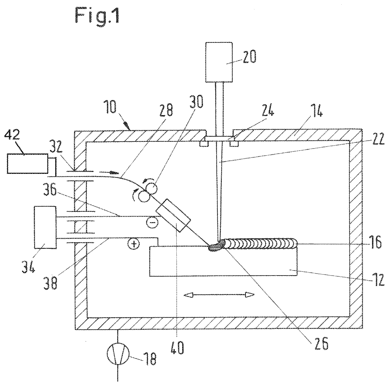
[0025]FIG. 1 shows a device 10 with which a method for the additive manufacture of a metallic component 12 in a vacuum chamber 14 can be performed. The component 12, which in FIG. 1 is shown still as a workpiece in an intermediate stage, is mounted on a table (not shown in any more detail) which permits a movement of the component in the X, Y and Z directions. The component 12 is generated in layered fashion in the context of the additive manufacture, that is to say, in the exemplary embodiment shown in FIG. 1, a series of layers has already been applied, wherein the present applied material layer 16 has, for illustrative purposes, been illustrated on an exaggeratedly large scale. The first layer may be built up on a substrate that has been introduced into the chamber 14 beforehand.

[0026]A vacuum pump 18 evacuates the interior of the vacuum chamber 14 to the pressure values that are conventional in the field of thermal processing methods in a vacuum.

[0027]The introduction of energy ...


PUM

PropertyMeasurementUnit
Polarityaaaaaaaaaa
Currentaaaaaaaaaa
Solidus temperatureaaaaaaaaaa

Abstract

The invention relates to a method for the additive manufacture of three-dimensional metallic components (12), said components (12) being built layer-by-layer or section-by-section under vacuum conditions by fusing a metallic material with the component (12) at a machining point by means of a radiation source with a high energy density. In order to keep the energy applied to the machining point by the radiation itself relatively low, the metallic material is supplied in the form of a wire (28) which is preheated under vacuum conditions before reaching the machining point.

Description

RELATED APPLICATIONS[0001]This application is a National Phase of PCT Patent Application No. PCT / EP2016 / 065757 having International filing date of Jul. 5, 2016, which claims the benefit of priority of German Patent Application No. 10 2015 008 919.6 filed on Jul. 15, 2015. The contents of the above applications are all incorporated by reference as if fully set forth herein in their entirety.FIELD AND BACKGROUND OF THE INVENTION[0002]The present invention relates to a method for the additive manufacture of three-dimensional metallic components, wherein the components are built up in layers or sections under vacuum conditions by fusion of a metallic material with the component at a processing location by means of a radiation source with high energy density.[0003]Such methods are known for example from EP 1 296 788 B1 or DE 10 2013 108 111 A1. Proceeding from a substrate as a starting point for the body to be manufactured, such as can also be used in the case of the present invention, t...

Claims


Application Information

Patent Timeline
IPC IPC(8): B23K26/34B23K26/12B33Y10/00B33Y40/00B23K15/00B23K26/08B23K15/06B23K26/342B22F3/105B23K26/354
CPCB23K26/34B22F3/1055B23K15/002B23K15/0086B23K15/06B23K26/0861B23K26/127B23K26/1224B23K26/342B23K26/354B33Y10/00B33Y40/00B22F2999/00Y02P10/25B22F12/13B22F10/25B22F10/32B33Y40/10B22F2201/20B22F2202/07
Inventor WAHL, MATTHIASWEIL, ALEXANDER
Owner EVOBEAM
Why Eureka
Try Eureka