Dual fuel injection system for optimizing fuel usage and minimizing slip for diesel engines

a dual fuel injection and fuel consumption technology, applied in the direction of electric control, machines/engines, mechanical equipment, etc., can solve the problems of reducing the efficiency of the engine, reducing the total amount of undesirable emissions produced by the engine, and reducing the production of undesirable emissions, so as to reduce slip, improve efficiency, and reduce emissions

Active Publication Date: 2021-01-12
DYNAMIC FUEL SYST
View PDF28 Cites 7 Cited by
  • Summary
  • Abstract
  • Description
  • Claims
  • Application Information

AI Technical Summary

Benefits of technology

[0027]Briefly, the invention involves a system and method for providing a liquid fuel or a liquid and gaseous fuel to a diesel cycle or Otto cycle engine for operation of the engine. The system includes a primary electronic control module (ECM) which monitors engine sensors and contains a first three-dimensional (3D) fuel map for the liquid fuel. A second ECM is connected for bi-directional transfer of information to the first ECM; the second ECM contains a second three-dimensional fuel map for delivery of the gaseous fuel through a secondary gaseous fuel injection assembly. The bi-directional communication between the two ECMs while monitoring the engine sensors allows both ECMs to “learn” an efficient fuel map for delivery of both fuels in the same cycle for improved efficiency, reduction in slip and lower emissions.
[0033]It is another objective of the instant invention to provide a gaseous fuel nozzle that allows for late injection to reduce slip.

Problems solved by technology

Further, combustion of the gaseous fuel and liquid fuel mixture lowers the production of undesirable emissions from the engine.
The fuel that escapes from the combustion chambers does not participate in combustion, reducing the efficiency of the engine.
Additionally, the escaping unburned gaseous fuel contributes to the total amount of undesirable emissions produced by the engine.
Although the '640 publication discloses the use of a processing unit to treat unburned gaseous fuel for improving engine emissions, the disclosed apparatus and method may still not be optimal.
Thus, the unburned gaseous fuel does not contribute to generation of power in the engine, reducing the efficiency of the engine.
Further, the disclosed apparatus of the '640 publication requires the use of additional ducting and the use of a processing unit, which may increase the cost of manufacturing and operating the engine.
However, typical speed controllers (usually proportional-integral controllers, commonly called PI controllers) may only set a fuel rate for a single fuel.
The disadvantages of this type of control structure include the significant amount of design time and effort required for multiple PI controllers and the complexity of the switching strategy to ensure that the overall design is robust and responsive to changes in the input power requirements.
Under such circumstances, the fuel flow rate determined based on the input fuel properties may not be accurate.

Method used


Image

  • Dual fuel injection system for optimizing fuel usage and minimizing slip for diesel engines
  • Dual fuel injection system for optimizing fuel usage and minimizing slip for diesel engines
  • Dual fuel injection system for optimizing fuel usage and minimizing slip for diesel engines

Examples


Embodiment Construction

[0049]While the present invention is susceptible of embodiment in various forms, there is shown in the drawings and will hereinafter be described a presently preferred embodiment with the understanding that the present disclosure is to be considered an exemplification of the invention, and is not intended to limit the invention to the specific embodiments illustrated.

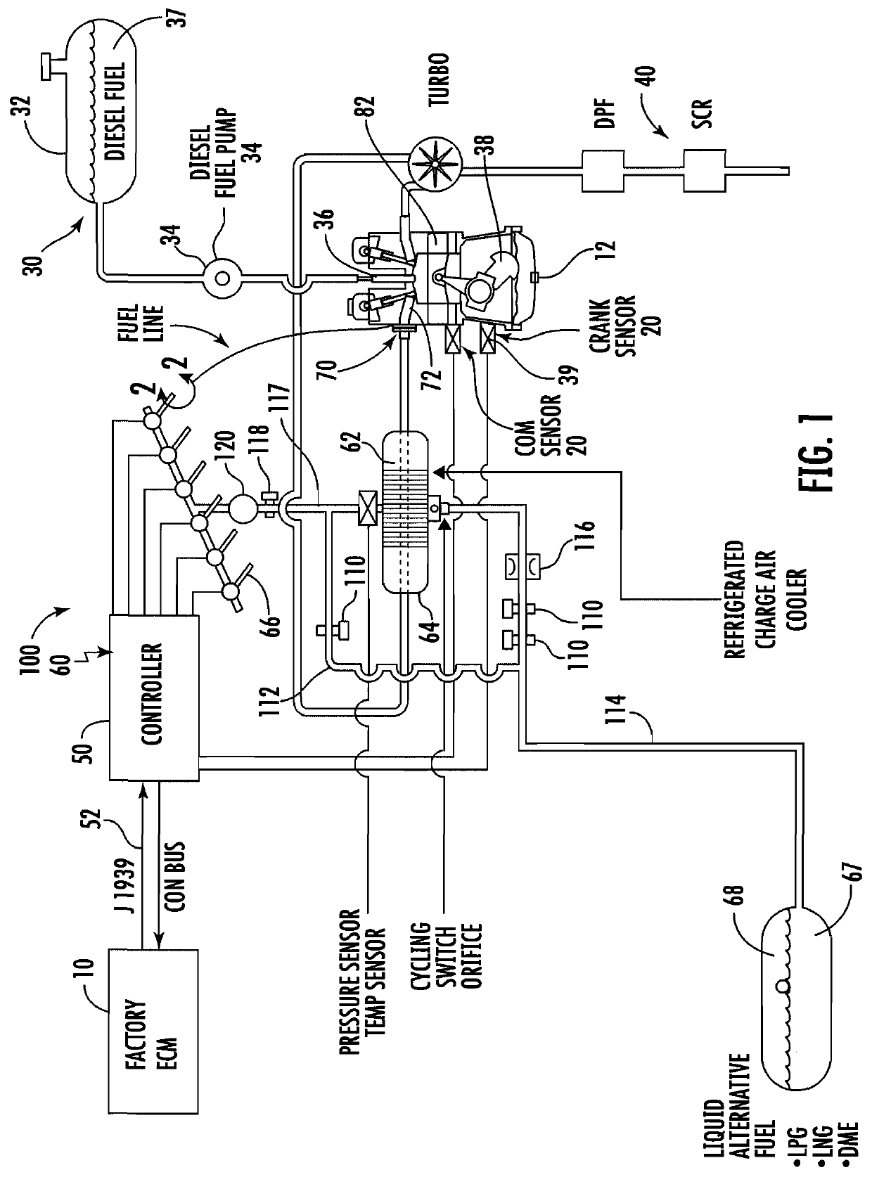
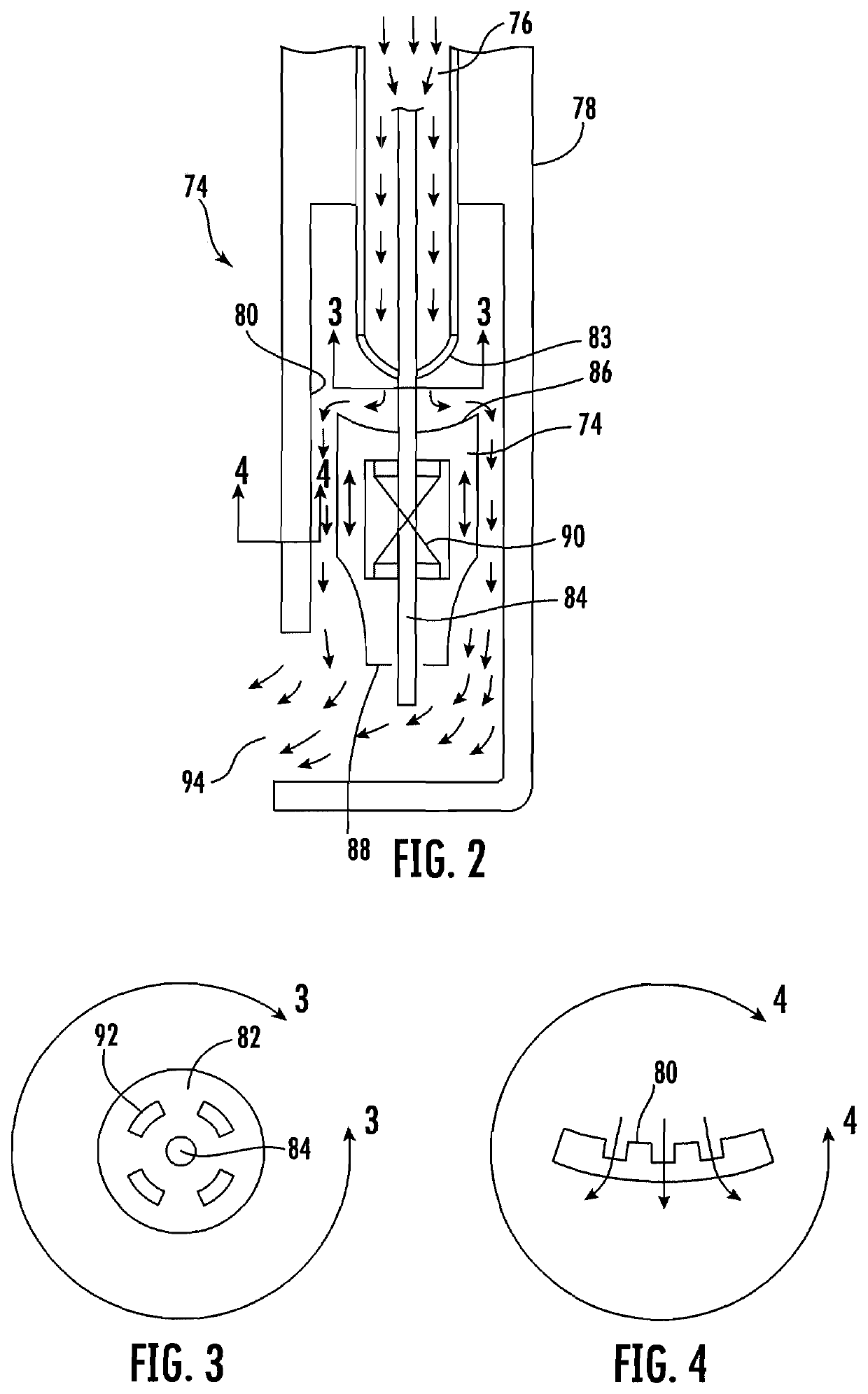
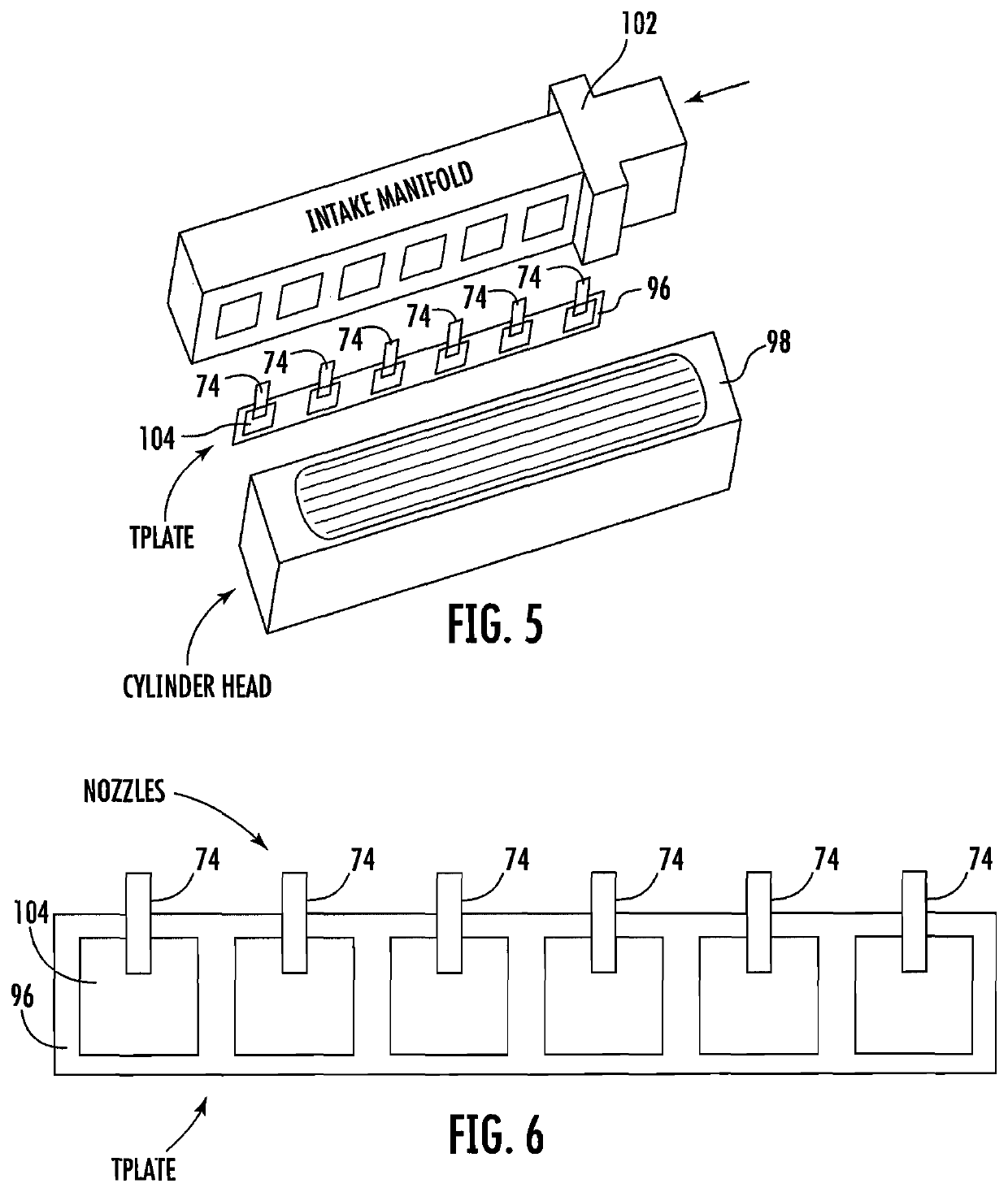
[0050]Referring generally to FIGS. 1-8, a liquid and gaseous fuel system 100 for a diesel engine 12 is illustrated. The system includes an engine control module (ECM) 10 in electrical communication with a plurality of diesel engine sensors 20, a liquid fuel system 30, and an exhaust system 40. The liquid fuel system 30 includes a liquid fuel tank 32, a liquid fuel pump 34 and at least one liquid fuel injector 36 configured to deliver more than a pilot amount of liquid diesel fuel to the diesel engine 12 in accordance with a liquid fuel map stored in the engine control module 10 and feedback from the diesel engine sensor...


PUM


Abstract

The invention involves a system and method for providing a liquid fuel or a liquid and gaseous fuel to a diesel or Otto cycle engine for operation of the engine. The system includes a primary electronic control module (ECM), which monitors engine sensors and contains a first three-dimensional fuel map for the liquid fuel. A second ECM is connected for bi-directional transfer of information to the first ECM, the second ECM contains a second three-dimensional fuel map for delivery of the gaseous fuel through a secondary gaseous fuel injection assembly. The bi-directional communication between the two ECMs while monitoring the engine sensors allows both ECMs to “learn” an efficient fuel map for delivery of both fuels in the same cycle for improved efficiency, reduction in slip and lower emissions.

Description

PRIORITY CLAIM[0001]In accordance with 37 C.F.R. 1.76, a claim of priority is included in an Application Data Sheet filed concurrently herewith. Accordingly, the present invention claims priority to U.S. Provisional Patent Application No. 62 / 613,552, entitled “DUAL FUEL INJECTION SYSTEM FOR OPTIMIZING FUEL USAGE AND MINIMIZING SLIP FOR DIESEL ENGINES”, filed Jan. 4, 2018. The contents of the above referenced application is incorporated herein by reference in its entirety.FIELD OF INVENTION[0002]The present invention generally relates to internal combustion engines, and more particularly, to an electronically controlled dual fuel injection system for dual fuel diesel and Otto cycle engines.BACKGROUND INFORMATION[0003]For more than a century, internal combustion engines have been relied upon as a principal source of power in a variety of applications. Of those engines, the most widely used are the reciprocating piston diesel engines which are found in automobiles, trucks, trains and e...

Claims


Application Information

Patent Timeline
Patent Type & Authority Patents(United States)
IPC IPC(8): F02D41/00F02D19/08F02B37/18F02D19/06F02M21/02F02D19/10F02M21/06
CPCF02B37/18F02D19/0694F02D19/081F02D19/105F02D41/0025F02D41/0027F02M21/0212F02M21/06F02D19/066F02D19/0647F02D19/0673F02D2400/11F02B29/045Y02T10/12Y02T10/30
Inventor BACH, JEFFREY R.
Owner DYNAMIC FUEL SYST
Why Eureka
Try Eureka