Nano-scale conical traps based splitter, combiner, and reflector, and applications utilizing same

a conical trap and nano-scale technology, applied in the field of optical nanostructures, can solve the problems of inability to realize the effect of a single frequency, inability to manufacture bragg mirrors, and inability to detect normal incidence, etc., and achieve the effect of extending the ability to perform such operations

Active Publication Date: 2021-02-02
WERTSBERGER SHALOM
View PDF93 Cites 0 Cited by
  • Summary
  • Abstract
  • Description
  • Claims
  • Application Information

AI Technical Summary

Benefits of technology

[0027]It is a further object of the present invention to provide a conical trap which is easily manufactured, and which refracts energy into spatially separated component frequencies and / or polarizations. It is another object of the present invention to provide a refractor that will steer the incoming energy from the incidence direction or acceptance cone of a substrate and radiate the spatially separated energy at various depths and / or angles from the incidence direction of the conical trap. An optional object of the invention is to dispose the conical trap in a substrate and direct the spatially separated spectral components to separate transducers.
[0028]It is a further object of the invention to provide a compact optical mixer / combiner that will combine radiant energy components from a plurality of sources at various locations and / or angles from the normal incidence direction of the cavity, and output the combined radiation from a single aperture.
[0030]It is yet another object of the invention to provide selective absorption and / or reflection of portions of an incoming spectrum of radiant energy entering the tapered cavity, so as to provide passive reflection of lights as required for a passive display device. Alternatively, the structure may absorb energy of one or more portions of the spectrum, reducing reflection of such energy.
[0052]Another aspect of the invention relates to phased array antennas. Phased array antennas operate on principles of interference between the radiant energy emitted from various antenna elements. Such interference may be created by manipulating the phase and / or amplitude of the signal emitted form a plurality of antenna elements. The steering of the antenna offers the ability to radiate extremely narrow beam which in certain embodiments may be utilized for writing or marking very small features such as features used in the photolithography. The small size of the individual CTs and their ability to provide high intensity signals make the CT based phased array a powerful tool. By way of example, an array of CTs dimensioned to operate at the UV range would be very small as each antenna element would be just over half of the longest emitted wavelength. In this type of phased array only a single transducer may be used per CT, however a plurality of transducers may provide better resolution. UV lasers coupled to separate CTs or to one CT, may be individually controlled and fed different phase and / or amplitude signals, and their interference would allow for a beam to form features that are far smaller than the wavelength. Such arrays may also be used for writing of certain images, for ablating material in a programmatic manner, as well as form scanning beams such as radar and the like. Similarly, in much lower frequencies radar type antennas may be formed by a plurality of CT's dimensioned properly for the operating frequency, wherein the compact size and high efficiency can provide an improved radar antennas used for transmitting and / or receiving. High directionality communications antennas of various frequencies may also be formed utilizing CT's.
[0056]The broad band capabilities of the CT allows modulation of its reflectance, absorption, or transmittance over a broad band of frequencies, extending the ability for such operations into the UV, IR, and even the mm wave, EHF and SHF spectrum. Reflective mode may also operate in polarization sensitive mode as explained above for EL and LE transducers in polarization sensitive mode.

Problems solved by technology

Normal incidence has the limitation of a finite probability of detecting energy before it is transmitted through the conversion layer.
Energy transmitted through the conversion layer is, at best, lost and, at worst, converted to heat in the supporting substrate.
Notably, Bragg mirrors are very frequency selective, complex to manufacture, and require at least a width higher than ¾ wavelength to provide any breadth of spectrum.
However the known art does not provide a multi purpose small scale splitter / combiner / reflector of radiant energy, and therefore it does not disclose applications of such splitter / combiner / reflector in combination with transducers embedded in a stratum, or a splitter in a non-absorbent stratum.

Method used


Image

  • Nano-scale conical traps based splitter, combiner, and reflector, and applications utilizing same
  • Nano-scale conical traps based splitter, combiner, and reflector, and applications utilizing same
  • Nano-scale conical traps based splitter, combiner, and reflector, and applications utilizing same

Examples


Embodiment Construction

lass="d_n">[0085]Certain figures and embodiments of the invention will be described herein by way of example to increase the understanding of different aspects of the invention.

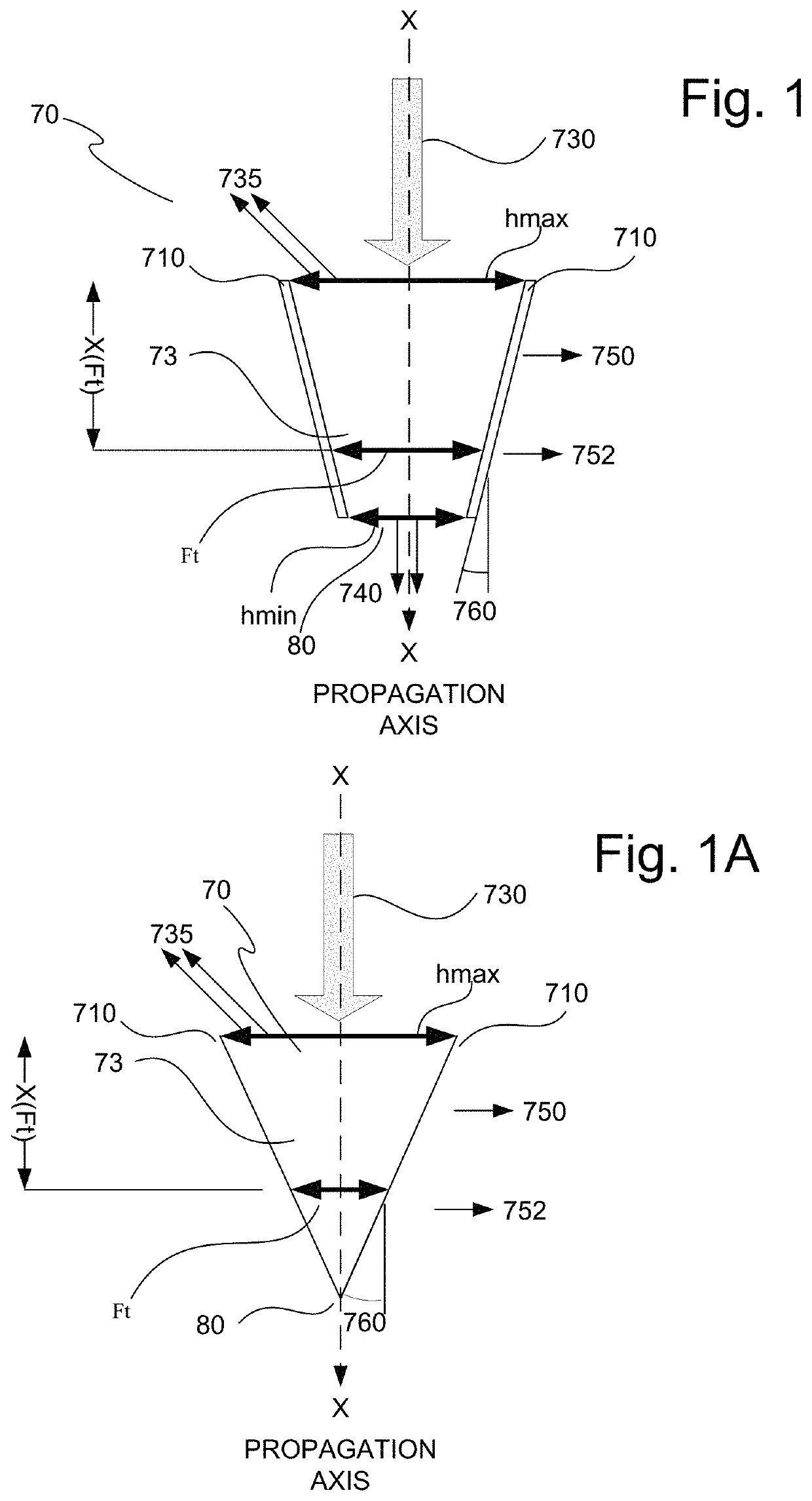
[0086]FIG. 1 depicts a cutout of a simplified conical trap (CT) 70 which is a cavity 73 having a tapered longitudinal cross section, and is dimensioned as described below. In splitter mode the CT allows a wave in the spectral range of interest to propagate in the cavity until it reaches a cone departure state CDP at a frequency dependent width, which corresponds to a frequency dependent depth due to the core taper. The cavity is dimensioned to allow the wave to propagate therein and to depart it via its peripheral side wall 710. The tapered cavity 73 has a wide end denoted in FIG. 1 as hmax defining an aperture, and a narrow end hmin referred to in theses specifications as a tip. The cavity is delimited by its side periphery walls 710 which in some embodiments are defined by the stratum in which the CT is emb...


PUM

PropertyMeasurementUnit
wavelengthsaaaaaaaaaa
wavelengthaaaaaaaaaa
multispectral radiant energyaaaaaaaaaa

Abstract

Tapered cavity structures disposed within a stratum may be configured as a spectral component splitters, a spectral component combiners, and various combinations thereof including a reflective mode of operation. The tapered cavities have an aperture at their wider and a tip at the narrower, and are dimensioned such that multi-spectral radiant energy admitted into the cavity via the aperture would depart the tapered cavity via its side periphery at a depth and / or direction dependent on its frequency and / or its polarization, and that a plurality of spectral components admitted to the cavities via the its peripheral side or sides will be mixed and emitted via the aperture. Reflective type structures where portions of radiant energy is selectively absorbed and other portions are reflected are also considered. Differing stratums are disclosed. Applications of the tapered cavities in a stratum are also disclosed.

Description

RELATED APPLICATIONS[0001]This application claims the right of priority to U.S. patent application No. 62 / 346,123 filed Jun. 6, 2017.[0002]Aspects relating to the present invention were first disclosed in U.S. Patent Application 61 / 701,687 to Andle and Wertsberger, entitled “Continuous Resonant Trap Refractor, Waveguide Based Energy Detectors, Energy Conversion Cells, and Display Panels Using Same”, filed 16 Sep. 2012. Further refinements of the tapered waveguide based Continuous Resonant Trap Refractor (CRTR) and to lateral waveguides with which CRTRs may cooperate, were disclosed together with various practical applications thereof in the following additional U.S. Patent Applications 61 / 713,602, entitled “Image Array Sensor”, filed 14 Oct. 2012; 61 / 718,181, entitled “Nano-Scale Continuous Resonance Trap Refractor”, filed 24 Oct. 2012; 61 / 723,832, entitled “Pixel Structure Using Tapered Light Waveguides, Displays, Display Panels, and Devices Using Same”, filed 8 Nov. 2012; 61 / 723,7...

Claims


Application Information

Patent Timeline
Patent Type & Authority Patents(United States)
IPC IPC(8): G02B27/10G02B27/00G02B6/10G02B6/12G02B6/122G02B6/293
CPCG02B27/1006G02B6/107G02B6/12011G02B6/12014G02B6/1228G02B6/293G02B27/0087G02B6/29304
Inventor WERTSBERGER, SHALOM
Owner WERTSBERGER SHALOM
Why Eureka
Try Eureka