Punching method, punching device, and method for manufacturing laminated iron core

a technology of laminated iron and punching device, which is applied in the direction of metal-working feeding device, manufacturing tools, magnetic bodies, etc., can solve the problems of deteriorating magnetic characteristics, plastic strain remaining in the vicinity of the punching end portion, and deteriorating the magnetic characteristics of the iron core, so as to reduce the deterioration of iron loss

Active Publication Date: 2021-02-16
JFE STEEL CORP
View PDF44 Cites 0 Cited by
  • Summary
  • Abstract
  • Description
  • Claims
  • Application Information

AI Technical Summary

Benefits of technology

[0019]Furthermore, the technique disclosed in Patent Literature 6 has aimed at reduction in abrasion of a mold when the steel sheets are stacked and punched out and has not studied a solution for preventing the deterioration in the magnetic characteristics in the punching. With the technique, the punching is performed in the state in which the steel sheets are bonded to each other and a process mode thereof is different from that in which the steel sheets are stacked immediately before being pressed and are subject to the punching. The technique disclosed in Patent Literature 7 has aimed at prevention of the deterioration in the magnetic characteristics of the iron core that occurs when the split iron core is manufactured and has not taken punching of a plurality of stacked steel sheets into consideration.
[0020]The present invention has been made in view of the above-mentioned circumstances and an object thereof is to provide a punching method, a punching device, and a laminated iron core manufacturing method capable of simultaneously punching a plurality of stacked electrical steel sheets while decreasing deterioration in iron loss to the minimum.
[0027]According to the present invention, a plurality of stacked electrical steel sheets can be simultaneously punched out while decreasing deterioration in iron loss to the minimum.

Problems solved by technology

It is generally known that plastic strain remains in the vicinity of punched end portions and magnetic characteristics are deteriorated therein because the punched end portions receive strong plastic deformation in the punching.
Thus, the punching is excellent in productivity but has a problem in that it deteriorates the magnetic characteristics of the iron core.
When a plurality of stacked steel sheets are subject to the punching, binding force between the stacked steel sheets is weak and a plastically deformed portion is therefore enlarged, resulting in deterioration in the magnetic characteristics in comparison with the case in which the punching is performed on the sheets one by one.
Accordingly, when the electrical steel sheets are stacked and simultaneously punched out, a problem of deterioration in the magnetic characteristics of the iron core occurs.
The above-mentioned techniques disclosed in Patent Literatures 1 to 5 have focused attention on only deterioration in the dimensional accuracy of the iron core and increase in the amounts of the shear droop and the burrs due to the punching of the steel sheets and disclose no improvement solution related to the deterioration in the magnetic characteristics of the iron core.
These techniques have an advantage from a viewpoint of the deterioration in the magnetic characteristics but have a disadvantage that the mold configuration is complicated and the mold cost is largely increased.
Furthermore, these techniques do not disclose a method for efficiently integrating and binding a plurality of iron core element pieces provided by punching with the punches and dies.
Furthermore, the technique disclosed in Patent Literature 6 has aimed at reduction in abrasion of a mold when the steel sheets are stacked and punched out and has not studied a solution for preventing the deterioration in the magnetic characteristics in the punching.

Method used


Image

  • Punching method, punching device, and method for manufacturing laminated iron core
  • Punching method, punching device, and method for manufacturing laminated iron core
  • Punching method, punching device, and method for manufacturing laminated iron core

Examples


examples

[0091]Hereinafter, examples of the present invention will be described. Among the examples below, those that satisfy the requirements of the present invention correspond to inventive examples and those that do not satisfy the requirements of the present invention correspond to comparative examples.

first example

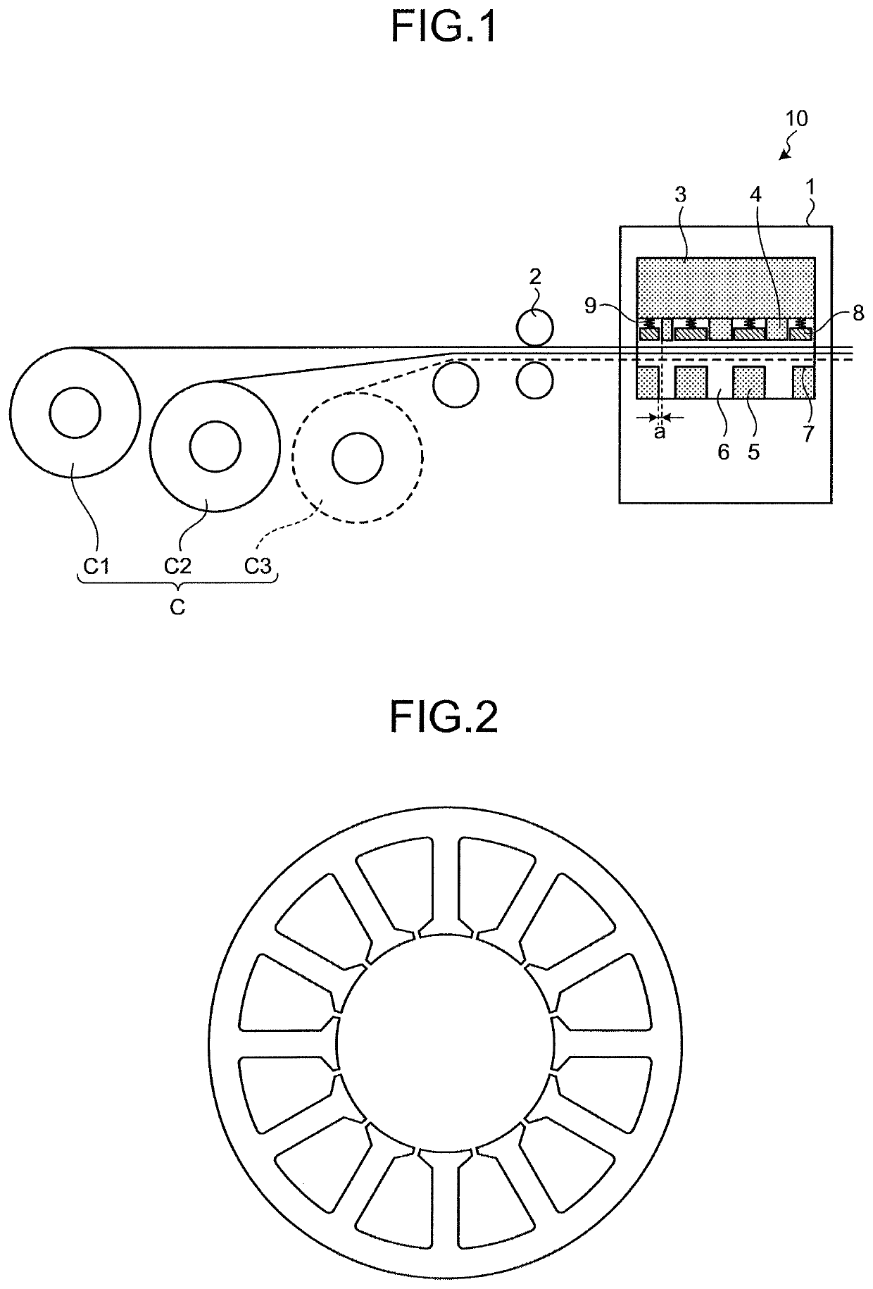
[0092]Two steel strip coils for punching work that were provided by slitting an electrical steel sheet coil containing Si of 3.0%, Al of 0.8%, Mn of 0.7%, and P of 0.03% in terms of mass ratio in steel and having a sheet thickness of 0.25 mm so as to have widths of 160 mm were prepared as the base material steel sheets. The two steel strip coils (C1 and C2) were simultaneously subject to the punching using the punching device 10 illustrated in FIG. 1 (work method: punching of two stacked sheets). The iron core element pieces provided by the punching were subject to interlocking in the mold 3 to manufacture a stator iron core for a brushless DC motor (motor core) illustrated in FIG. 2.

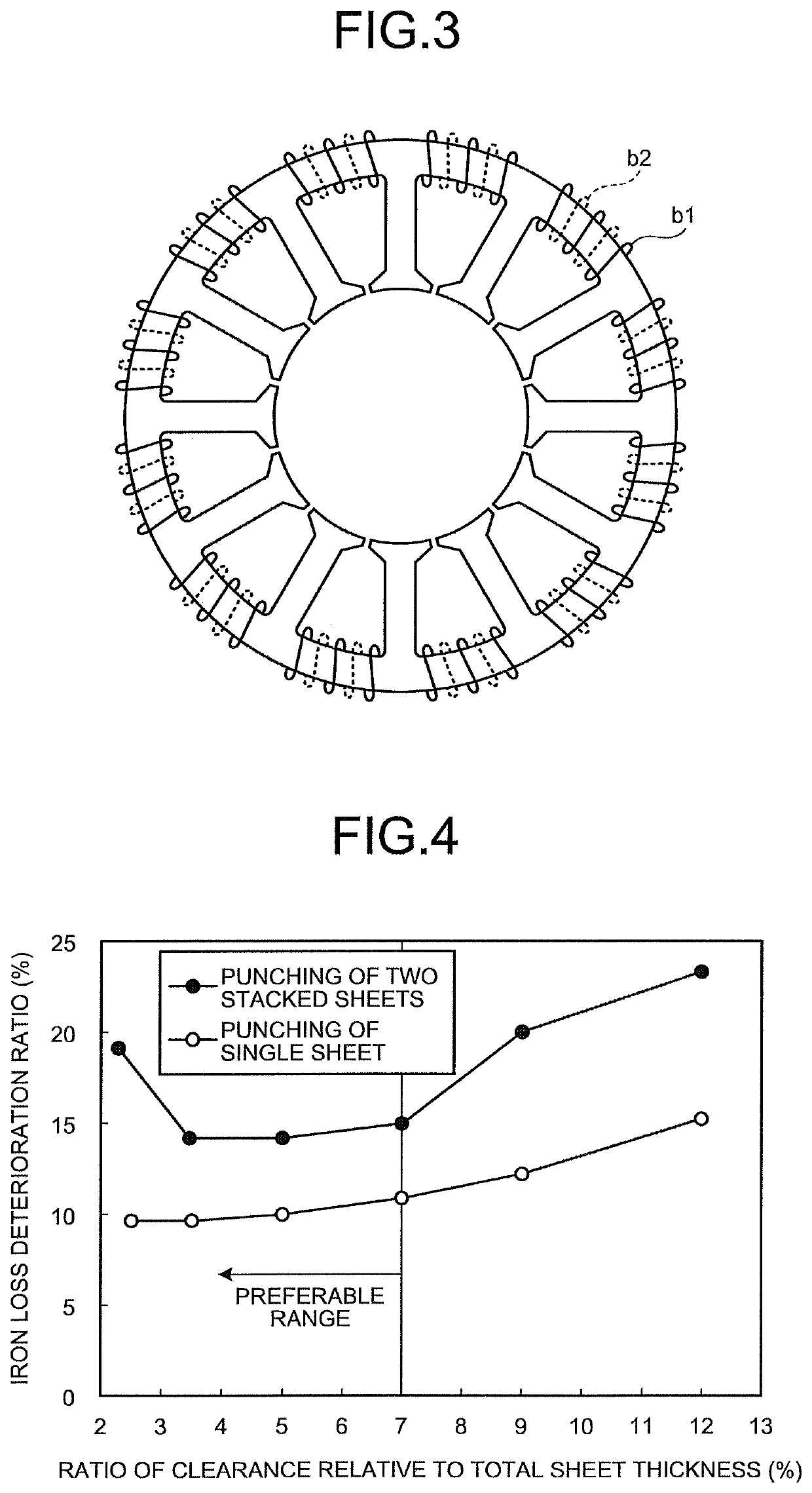
[0093]The clearance (one side) a in the punching was made to vary in a range of 2 to 15% relative to the total sheet thickness of 0.50 mm of the two electrical steel sheets. The pressure (sheet presser pressure) that the sheet presser 8 applies to the electrical steel sheets in the mold 3 was made to va...

second example

[0099]Steel strip coils for punching work that were provided slitting electrical steel sheet coils having different crystal grain sizes with varied contents of Si, Al, Mn, and P in steel and having sheet thicknesses of 0.35 mm, 0.25 mm, 0.20 mm, and 0.15 mm so as to have widths of 160 mm were prepared as the base material steel sheets. The two steel strip coils (C1 and C2) of a varied combination among them were simultaneously subject to the punching using the punching device 10 illustrated in FIG. 1. Outer peripheral portions of the iron core element pieces provided by the punching were welded to manufacture a stator iron core for a brushless DC motor (motor core). The clearance (one side) a in the punching was set to 25 μm (5% of the total sheet thickness of the two sheets) and the pressure (sheet presser pressure) that the sheet presser 8 applies to the material in the mold 3 was set to 0.35 MPa.

[0100]As a comparative example, in order to evaluate deterioration in the magnetic ch...


PUM

PropertyMeasurementUnit
average crystal grain sizeaaaaaaaaaa
thicknessaaaaaaaaaa
pressureaaaaaaaaaa

Abstract

A punching method includes: punching out a plurality of electrical steel sheets in a stacked state by a mold, wherein sheet thicknesses of the electrical steel sheets are set to be 0.35 mm or less, a Vickers hardness (test force 1 kg) of the sheets is set to be 150 to 400, and an average crystal grain size of the sheets is set to be 50 to 250 μm, a clearance of the mold is set to be 7% or more of a minimum sheet thickness of the sheet thicknesses of the electrical steel sheets and equal to or lower than 7% of a total sheet thickness of the electrical steel sheets, and a pressure that a sheet presser of the mold applies to the electrical steel sheets is set to be 0.10 MPa or more.

Description

CROSS REFERENCE TO RELATED APPLICATIONS[0001]This application is the U.S. National Phase application of PCT International Application No. PCT / JP2016 / 050323, filed Jan. 7, 2016 and claims priority to Japanese Patent Application No. 2015-005233, filed Jan. 14, 2015, the disclosures of both applications being incorporated herein by reference in their entireties for all purposes.FIELD OF THE INVENTION[0002]The present invention relates to a punching method of an electrical steel sheet that is used for an iron core of a motor, a punching device, and a laminated iron core manufacturing method.BACKGROUND OF THE INVENTION[0003]In recent years, attempts have been made in reduction in size of iron cores in order to reduce weights of motors and generators of electric cars and hybrid electric cars mainly, and increase in rotation has been advanced (increase in frequency) for ensuring output. From a viewpoint of decreasing iron loss of the iron core, a thinner electrical steel sheet having a she...

Claims


Application Information

Patent Timeline
Patent Type & Authority Patents(United States)
IPC IPC(8): B21D28/14B26F1/42H01F1/147B21D43/28C22C38/00C22C38/06H01F41/02B21D35/00B21D28/22H01F41/061H01F1/16C22C38/60
CPCB21D28/14B21D28/22B21D35/005B21D35/007B26F1/42C22C38/00C22C38/06H01F1/14716H01F41/02H01F41/061B21D43/287C22C38/60H01F1/16Y02T10/64H01F41/0233B21D28/02B21D28/00
Inventor SENDA, KUNIHIROUESAKA, MASANORIODA, YOSHIHIKO
Owner JFE STEEL CORP
Why Eureka
Try Eureka