System and method for diagnosing a variable displacement engine

a variable displacement, engine technology, applied in the direction of machines/engines, electric control, combustion air/fuel air treatment, etc., can solve the problems of increased risk of engine cylinder valve leakage, increased possibility of degradation of one or more valve actuators that selectively activate and deactivate engine cylinder valves, and increased risk of engine cylinder leakage, so as to reduce engine pumping losses, improve thermal efficiency, and increase the efficiency of cylinders that remain active

Active Publication Date: 2021-03-23
FORD GLOBAL TECH LLC
View PDF21 Cites 1 Cited by
  • Summary
  • Abstract
  • Description
  • Claims
  • Application Information

AI Technical Summary

Benefits of technology

[0001]Cylinders of an engine may be selectively deactivated to conserve fuel while other cylinders continue to operate to propel a vehicle and to keep the engine rotating. The cylinders may be deactivated by holding intake and exhaust valves of deactivated cylinders in a closed state over an entire engine cycle (e.g., two revolutions for a four stroke engine). Efficiency of cylinders that remain activated increases by improving thermal efficiency and reducing engine pumping losses. Selected cylinders may be deactivated and reactivated responsive to driver demand torque and other vehicle operating conditions. For example, at low engine loads, an eight cylinder engine may combust air and fuel in four cylinders. On the other hand, the same eight cylinder engine may combust air and fuel in all eight cylinders during high driver demand conditions. In other examples, a single cylinder may be deactivated at a time, the identity of the deactivated cylinder varied over a rolling window. In this way, a variable displacement engine (VDE) may enter and exit cylinder deactivation modes (also known as VDE modes) to accommodate different driving conditions.
[0006]In one example, the above issues may be at least partly addressed by an engine operating method, comprising: rotating an engine, unfueled, in a direction reversed from fueled engine rotation; and indicating valve actuator degradation responsive to an intake manifold pressure change rate, sensed without deactivating valves of a plurality of engine cylinders, being less than a threshold different from another intake manifold pressure change rate sensed while deactivating valves of at least one of the plurality of engine cylinders. In this way, cylinder valve actuators may be diagnosed more frequently, and more reliably, while using existing sensors.
[0010]In this way, by rotating an engine or an electric intake compressor via an electric machine in a reverse direction and measuring engine air flow while the engine is rotating, it may be possible to provide the technical result of determining whether or not one or more cylinder valve actuator mechanisms are degraded. In particular, the reverse rotation may provide an increased amount of air flow through the engine as compared to if the engine were rotated in a forward direction because of inherent differences between intake and exhaust valve timing. The increased air flow may provide an improved signal to noise ratio so that valve actuator diagnostics may be improved. Further, a higher air flow rate through the engine may allow the engine to be rotated at a lower speed while still being able to detect cylinder valve actuator degradation reliably. The lower speed may conserve battery power, improving fuel economy. The technical effect of performing the diagnostic while the engine is not combusting fuel is that the interfering effect of poor combustion and degraded fuel injectors or spark plugs is also removed. By using a MAP (or MAF) sensor to determine the intake airflow profile during the reverse rotation while the engine is in the VDE mode, an existing sensor can be repurposed for the VDE diagnostic, reducing system cost and complexity. By comparing the air flow of a suspected cylinder(s) in a VDE mode with a baseline air flow established when the engine is operating with all cylinders active, a leaky exhaust valve of a deactivated cylinder can be identified with high fidelity, allowing for mitigating actions to be specified for the relevant cylinder.

Problems solved by technology

On the other hand, the same eight cylinder engine may combust air and fuel in all eight cylinders during high driver demand conditions.
Over time and varying vehicle operating conditions, the possibility of degradation of one or more valve actuators that selectively activate and deactivate engine cylinder valves may increase.
Exhaust valves may be more prone to leakage than intake valves due to higher levels of local carbon deposits.
If the valve actuator mechanism is faulty and the valves are not sealing properly, fuel economy is impacted as the inability to seal the cylinder results in a pumping loss which can offset the fuel economy gains from the VDE operation.
Continuing to run an engine with leaky exhaust valves from carbon build-up can also thermally damage the valve due to the combustion event releasing large amounts of heat around the valve edges.
Drivability issues may also arise as unaccounted air and / or fuel vapors are directed from the leaking cylinder toward an exhaust catalyst.
However, the inventors herein have identified potential issues with such an approach.
As one example, since the approach requires the actuation of the VDE mechanism, the opportunities to diagnose the VDE mechanism are limited.
As a result, it may not be possible to diagnose the VDE mechanism on the drive cycle.
However, such approaches may require expensive pressure sensors.
Still other methods that correlate the commanded change in induction state with sensed torque changes may lack sufficient clarity and resolution.
For example, it may be difficult to differentiate loss of torque due to VDE mechanism degradation from other factors that can contribute to loss of torque, such as cylinder misfire, fuel injector degradation, or spark plug degradation.
Further still, a signal to noise ratio for detecting cylinder valve actuator degradation may be low while the engine is operating because exhaust gas recirculation (EGR), barometric pressure, and other engine operating conditions may affect the signal to noise ratio of signals used to determine valve actuator degradation.

Method used


Image

  • System and method for diagnosing a variable displacement engine
  • System and method for diagnosing a variable displacement engine
  • System and method for diagnosing a variable displacement engine

Examples


Embodiment Construction

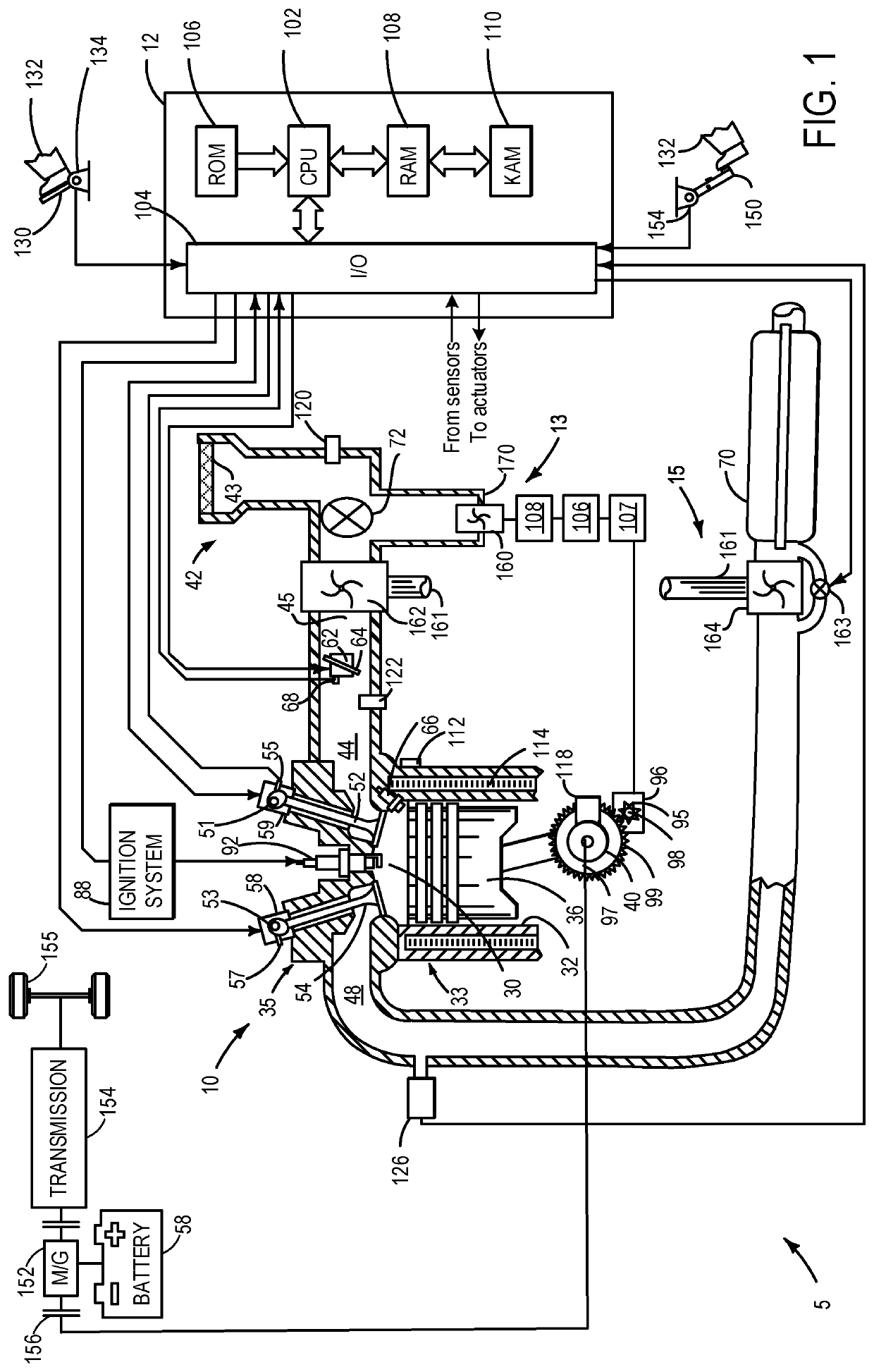
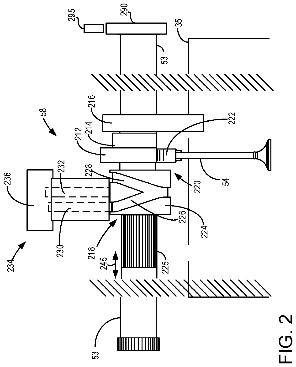
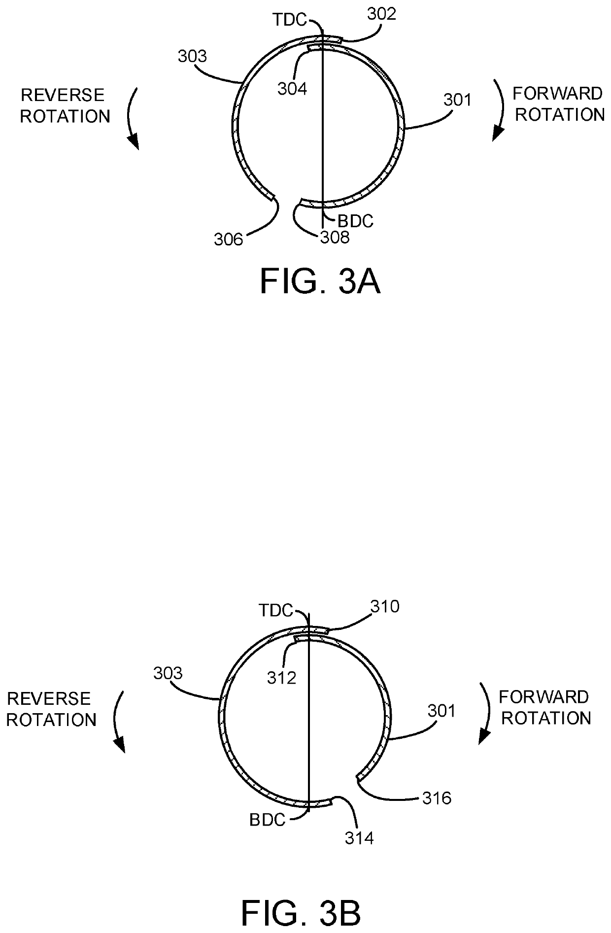
[0022]The present description is related to providing diagnosing operation of an engine that includes actuating mechanisms for cylinder valves, such as the engine system of FIG. 1. The actuating mechanisms may be included in the engine to selectively deactivate intake and exhaust valves of engine cylinders to activate and deactivate engine cylinder modes. An example actuating mechanism for cylinder valves is shown in FIG. 2. Example valve timings are shown in FIGS. 3A-3B while example engine cylinder configurations are shown in FIGS. 4A and 4B. An engine controller may perform a control routine, such as the example routines of FIGS. 5-6, to diagnose cylinder valve actuator degradation based on a change in intake manifold airflow while an engine or an electric booster is rotated in a reverse direction. Reverse rotation may be enabled via use of an H-bridge circuit, such as the circuit shown in FIGS. 7A-B. An example MAP profile that may be used for identifying valve actuator degradat...


PUM


Abstract

Systems and methods for determining operation of a cylinder deactivating / reactivating device are disclosed. In one example, a direction of engine rotation is selected to maximize air flow through the engine while the engine is rotated without combusting air and fuel. Operation of one or more cylinder valve deactivating mechanisms is assessed while the engine is rotated without combusting air and fuel.

Description

BACKGROUND AND SUMMARY[0001]Cylinders of an engine may be selectively deactivated to conserve fuel while other cylinders continue to operate to propel a vehicle and to keep the engine rotating. The cylinders may be deactivated by holding intake and exhaust valves of deactivated cylinders in a closed state over an entire engine cycle (e.g., two revolutions for a four stroke engine). Efficiency of cylinders that remain activated increases by improving thermal efficiency and reducing engine pumping losses. Selected cylinders may be deactivated and reactivated responsive to driver demand torque and other vehicle operating conditions. For example, at low engine loads, an eight cylinder engine may combust air and fuel in four cylinders. On the other hand, the same eight cylinder engine may combust air and fuel in all eight cylinders during high driver demand conditions. In other examples, a single cylinder may be deactivated at a time, the identity of the deactivated cylinder varied over ...

Claims


Application Information

Patent Timeline
Patent Type & Authority Patents(United States)
IPC IPC(8): F02D41/22F01L13/00F02M35/10F02B39/10F02D41/18F02D41/12F01L1/053
CPCF02D41/221F01L13/0005F02B39/10F02D41/18F02M35/1038F02M35/10386F01L2001/0537F01L2013/001F01L2013/0052F01L2013/101F01L2013/105F01L2800/11F01L2820/041F02D41/123F02D2200/0402F02D2200/0406F02D2250/06F02D13/06G01M15/09Y02T10/40
Inventor DUDAR, AED M.
Owner FORD GLOBAL TECH LLC
Why Eureka
Try Eureka