
Alloy for R—T—B based rare earth sintered magnet and method for producing the R—T—B based rare earth sintered magnet

a rare earth, sintered magnet technology, applied in the direction of magnetic materials, inductance/transformer/magnet manufacture, magnetic bodies, etc., can solve the problem that the alloy produced using the above-mentioned alloy cannot be further improved, the coercive force is not sufficiently generated, and the pulverizing conditions are limited to precisely control, etc. problem, to achieve the effect of suppressing abnormal grain growth and improving magnetic properties

Active Publication Date: 2021-03-30
TDK CORPARATION
View PDF6 Cites 0 Cited by
  • Summary
  • Abstract
  • Description
  • Claims
  • Application Information

AI Technical Summary

Benefits of technology

[0007]The present invention aims to obtain an alloy for R-T-B based rare earth sintered magnet to obtain an R-T-B based rare earth sintered magnet which improves magnetic properties (Br, Hcj or Hk / Hcj) while suppressing abnormal grain growth.
[0013]The alloy for R-T-B based rare-earth sintered magnet according to the present invention has the above-mentioned constitution, thereby the R-T-B based rare earth sintered magnet produced by the alloy for R-T-B based rare-earth sintered magnet according to the present invention becomes excellent in magnetic properties and improves Hk / Hcj, in addition.

Problems solved by technology

However, there is a limit to precisely control the pulverizing conditions.
Although Patent Document 1 provides an alloy controlling abnormal grain growth, due to the existence of R oxide in the alloy, an R-rich phase as a source of coercive force is not sufficiently generated, and that coercive force of R-T-B based rare earth sintered magnet produced using the above-mentioned alloy cannot be further improved.Patent Document 1: JP-A-2006-210893

Method used


Image

  • Alloy for R—T—B based rare earth sintered magnet and method for producing the R—T—B based rare earth sintered magnet
  • Alloy for R—T—B based rare earth sintered magnet and method for producing the R—T—B based rare earth sintered magnet
  • Alloy for R—T—B based rare earth sintered magnet and method for producing the R—T—B based rare earth sintered magnet

Examples


Embodiment Construction

"d_n">[0085]Hereinafter, the invention will be described in detail referring to concrete examples; however, the invention is not limited thereto.

[0086]According to the present examples, alloys of each example and comparative example were obtained by strip casting method. Specific methods are described below.

[0087]Nd, electrolytic iron and low carbon ferroboron alloy were prepared as raw material metals. Then, each raw material metal was weighed so that a mother alloy having a composition of Nd: 32.0 mass %, B: 1.0 mass % and the balance being Fe was obtained. Then, high-frequency melting was performed in an alumina crucible. During high-frequency melting, making the alloy melting temperature as Tm, a molten alloy was obtained by heating and melting at the high-frequency melting temperatures shown in Table 1. Although the alloy melting temperature Tm varies in each example and the comparative example, the alloy melting temperature Tm was within the range of 1150° C. or more and 1350°...


PUM

PropertyMeasurementUnit
lengthaaaaaaaaaa
lengthaaaaaaaaaa
lengthaaaaaaaaaa

Abstract

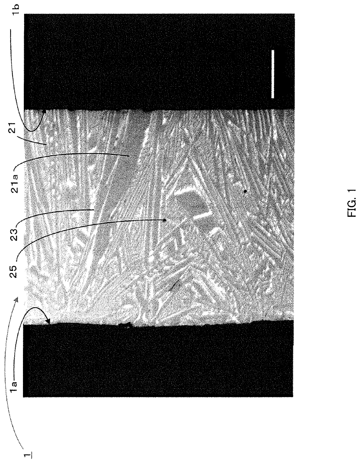
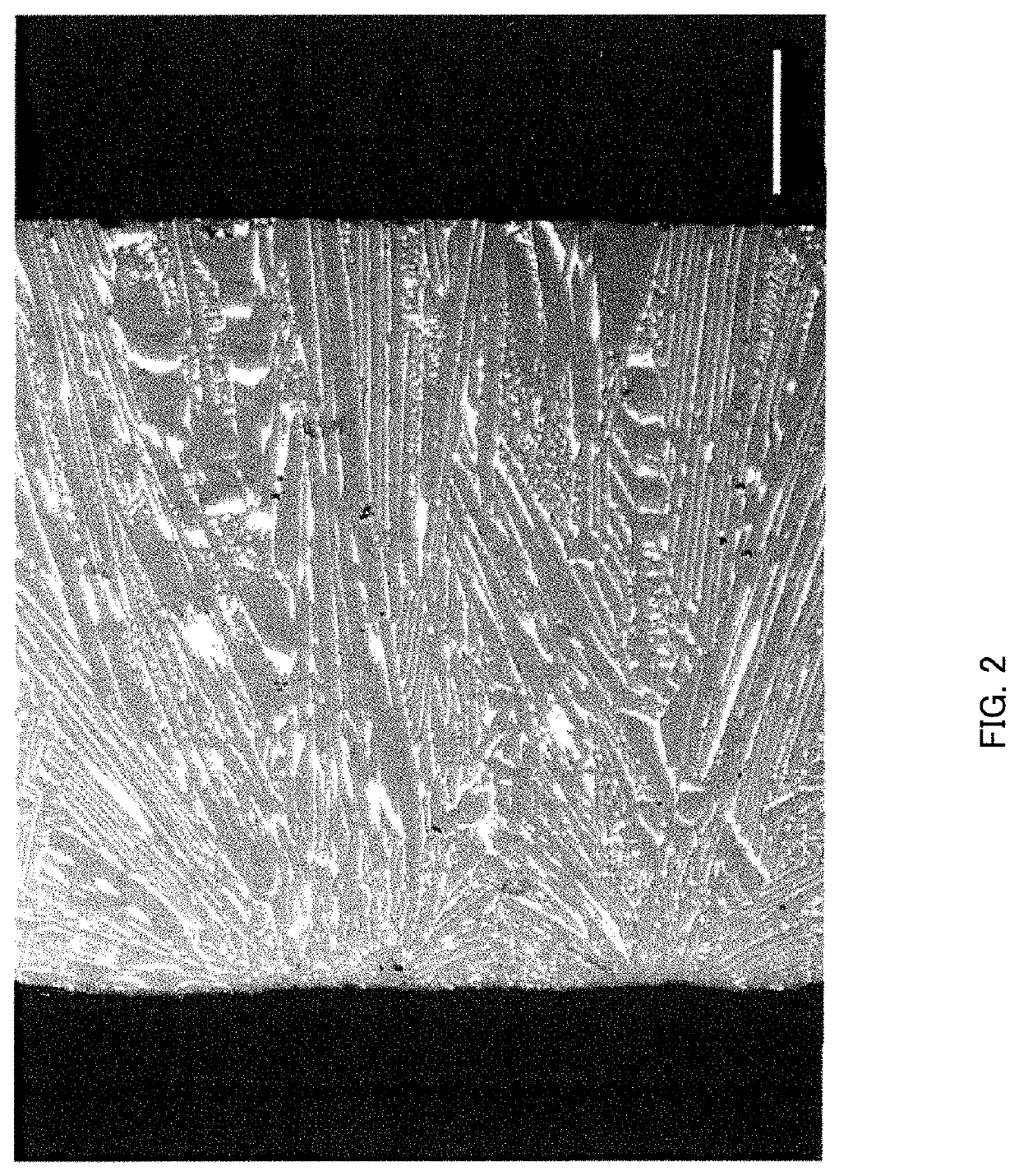
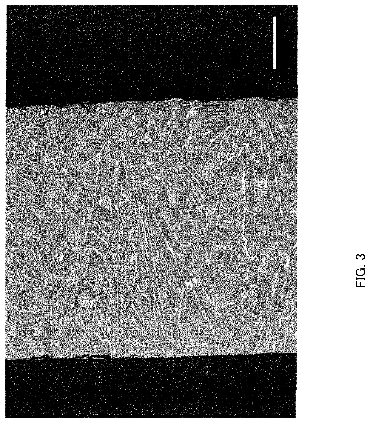
Provided is an alloy for R-T-B based rare earth magnet. “R” is one or more of a rare earth element, ‘T’ is one or more of a transition metal element essentially including Fe or Fe and Co, and “B” is boron. The alloy includes a single or a plural number of main phase (A), having a minimum length of 10 μm or more and a maximum length of 30 μm or more and 300 μm or less, in a cross section cut along a thickness direction of the alloy. The main phase (A) includes an R2T14B phase, and an area ratio of the main phase (A) to an entire cross section is 2% or more and 60% or less.

Description

BACKGROUND OF THE INVENTION1. Field of the Invention[0001]The present invention relates to an alloy for R-T-B based rare earth sintered magnet and a method for producing the R-T-B based rare earth sintered magnet.2. Description of the Related Art[0002]The R-T-B based rare earth sintered magnets are known to have excellent magnetic properties. At present, further improvements of magnetic properties and squareness ratio are desired. In particular, controlling abnormal grain growth is important to improve the squareness ratio.[0003]Conventionally, the abnormal grain growth control has been carried out by controlling pulverized grain diameter by precisely controlling pulverizing conditions of a raw material alloy. However, there is a limit to precisely control the pulverizing conditions.[0004]It was also attempted to control pulverized grain diameter by controlling the raw material alloy structure to suppress abnormal grain growth. Patent Document 1 describing control of the raw materia...

Claims


Application Information

Patent Timeline
Patent Type & Authority Patents(United States)
IPC IPC(8): H01F1/057H01F41/02B22F3/16B22F9/04C22C38/00
CPCH01F1/0577H01F41/0266C22C38/005C22C2202/02H01F41/0253
Inventor HAYAKAWA, TAKUMAIWASAKI, MAKOTOHIDAKA, TETSUYAKATO, EIJIKITAOKA, HIDETAKE
Owner TDK CORPARATION
Learn More