Check patentability & draft patents in minutes with Patsnap Eureka AI!

Tool with linear drive mechanism, dual speed gearbox and elastomeric control system

a technology of linear drive mechanism and elastomeric control system, which is applied in the direction of manufacturing tools, mechanical equipment, and gearmaking, etc., can solve the problems of elongated tool housing and periodic inspection and maintenance requirements of hydraulic pumps

Active Publication Date: 2021-04-06
CREATIVE MOTION CONTROL +2
View PDF5 Cites 1 Cited by
  • Summary
  • Abstract
  • Description
  • Claims
  • Application Information

AI Technical Summary

Benefits of technology

The present invention provides a portable hand tool with a linear drive mechanism that is lightweight and compact. The tool features a roller screw mechanical linear drive mechanism coupled to its work implement. A variable ratio gearbox is attached to the drive tube and is automatically adjusted to change the gear ratio based on the motor torque output. A secondary motor is coupled to the outer ring gear to counteract the gear ratio of the planet gears. A torque adjustment and sensing system measures the load on the work implement and reduces the gear ratio when the load reaches a predetermined level, resulting in a decrease in the output speed and an increase in the output torque of the tool. The tool may also include a rechargeable battery for powering the primary and secondary motors.

Problems solved by technology

One drawback with power hand tools that use hydraulic pumps is the hydraulic pump's periodic inspection and maintenance requirements.
Another drawback is the tool's housing is elongated to accommodate the hydraulic pump, the linear mechanism and the working implement.

Method used


Image

  • Tool with linear drive mechanism, dual speed gearbox and elastomeric control system
  • Tool with linear drive mechanism, dual speed gearbox and elastomeric control system
  • Tool with linear drive mechanism, dual speed gearbox and elastomeric control system

Examples


Embodiment Construction

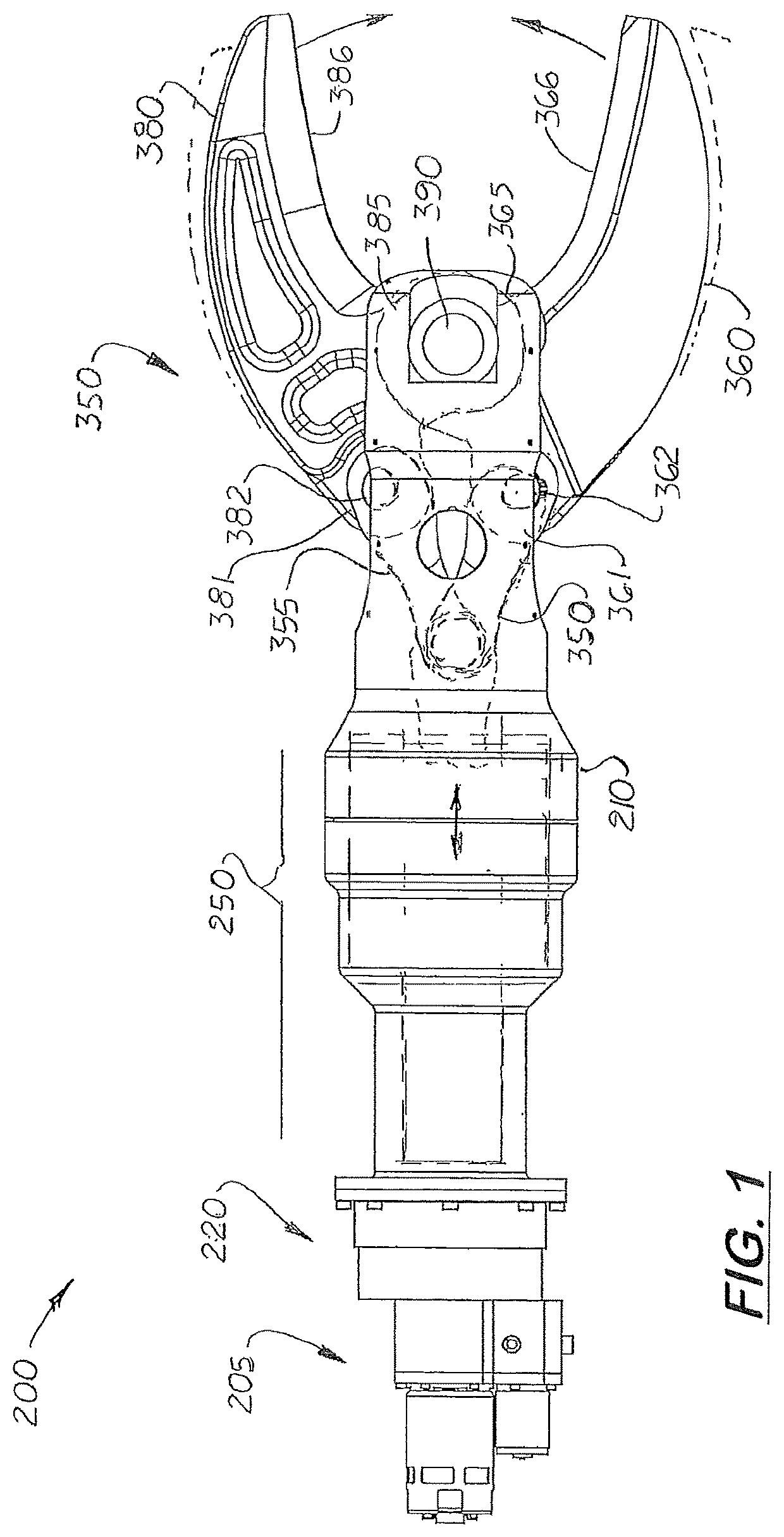
[0038]FIGS. 1-9 show a tool 200 with lightweight linear drive mechanism that uses an electric motor assembly 205 coupled to a multiple stage, self-regulating gear box 220. Coupled to the gear box 220 is a geared planetary roller screw 250. The geared planetary roller screw 250 is similar to the roller screw shown in U.S. Pat. No. 2,683,379 (Strandgren) which is now incorporated herein.

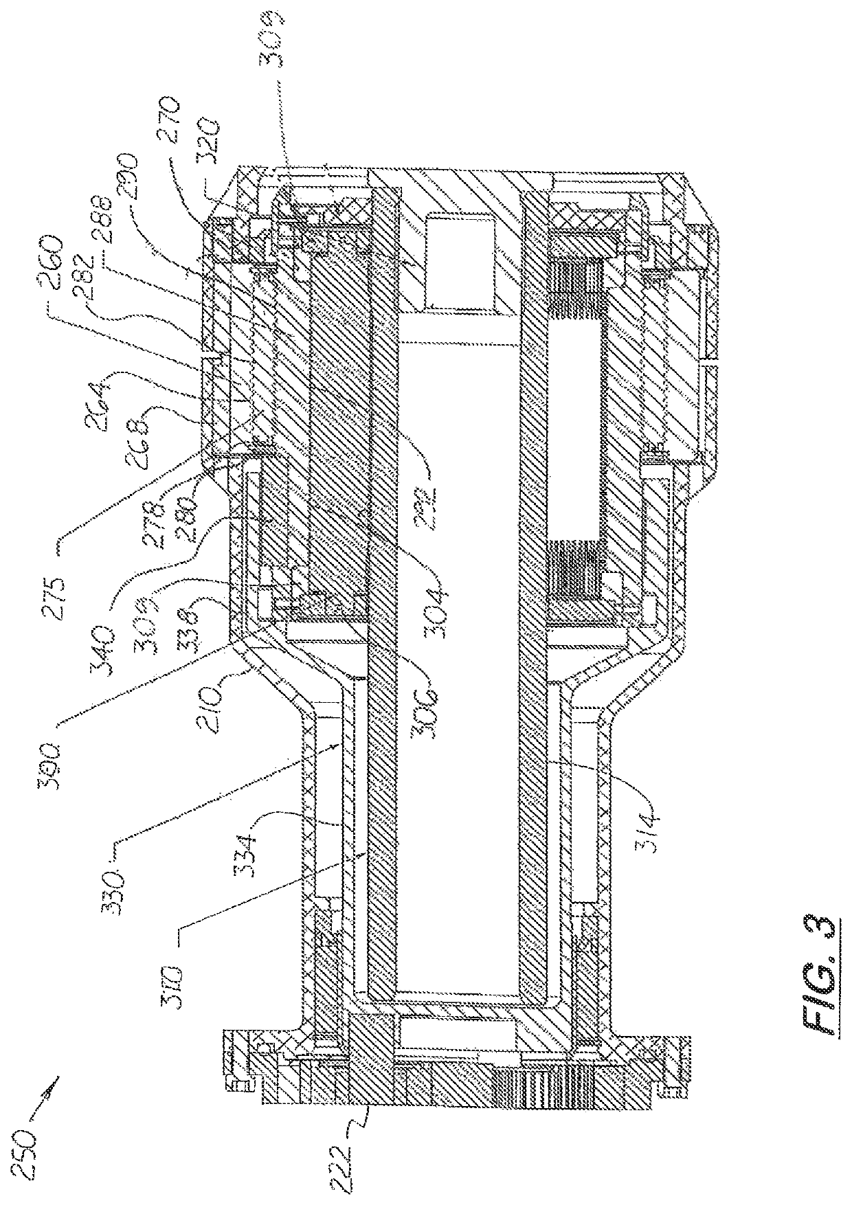
[0039]The geared planetary roller screw 250 includes a fixed cylindrical, fixed outer race 260 axially aligned inside the tool's outer housing 210. The outer race 260 includes a plurality of internal, non-helical grooves 264. A dowel pin 268 is inserted in between the outer housing 210 and the outer race 260 to hold the outer race 260 inside the tool 200. A set screw 270 is used to retain the dowel pin 268 in the outer housing 210.

[0040]Located adjacent inside the outer race 260 is a plurality of outer grooved rollers 275. Formed on each end of the outer grooved rollers 275 are axially aligned axles 27...


PUM

PropertyMeasurementUnit
linear movementaaaaaaaaaa
rotationaaaaaaaaaa
forceaaaaaaaaaa

Abstract

A hand tool with a mechanical linear drive mechanism coupled to a work implement. The drive mechanism includes a roller screw with a torque tube connected to a roller screw's nut body. The roller screw includes a fixed outer race, a rotating set of rollers axially aligned inside the outer race, a cylindrical nut body located inside the set of rollers, a plurality of inner rollers axially aligned and inside the nut body, a threaded shaft axially aligned and inside the inner rollers, and a torque tube axially aligned inside the inner rollers. The torque tube is connected to a multiple speed gearbox which includes a primary motor coupled to a carrier gear with three planet gears. Disposed around the planet gears is an outer ring gear. Coupled to the outer ring gear is a secondary motor which when activated causes the ring gear to rotate in the opposite direction of the planet gears.

Description

TECHNICAL FIELD[0001]This invention relates to linear drive mechanisms, and more particularly to linear drive mechanism that are portable and compact.BACKGROUND ART[0002]Portable hand tools are commonly used by emergency personnel to bend, spread or cut metal pieces to free drivers and passengers from their vehicles after accidents. The working implements on these hand tools are actuated by a linear mechanism coupled to a hydraulic cylinder. The hydraulic cylinder is coupled to a gas or electricity powered hydraulic pump.[0003]One drawback with power hand tools that use hydraulic pumps is the hydraulic pump's periodic inspection and maintenance requirements. Another drawback is the tool's housing is elongated to accommodate the hydraulic pump, the linear mechanism and the working implement.[0004]During use, the load exerted on the working implement on the hand tool varies. With hand tools that use hydraulic cylinders, check valves and by-pass valves are used to control the hydraulic...

Claims


Application Information

Patent Timeline
Patent Type & Authority Patents(United States)
IPC IPC(8): B23D17/04B23D29/00F16H25/20F16H25/22F16H3/72B23D29/02F16H37/12B25B7/12
CPCB23D17/04B23D29/00B23D29/02B25B7/12F16H3/727F16H25/2021F16H37/12F16H25/2252F16H2025/2081F16H2025/2087
Inventor LAWLOR, SHAWNCORNELIUS, CHARLES C
Owner CREATIVE MOTION CONTROL
Features
  • R&D
  • Intellectual Property
  • Life Sciences
  • Materials
  • Tech Scout
  • Unparalleled Data Quality
  • Higher Quality Content
  • 60% Fewer Hallucinations
Learn More