Electrically controlled nanomagnet and spin orbit torque magnetic random access memory including the same

a magnetic random access and magnetic random access technology, which is applied in the direction of electrical apparatus, galvano-magnetic hall-effect devices, and semiconductor devices, can solve the problems of limited conversion efficiency from charge to spin current, difficult scaling down the critical current for ns fast switching, and complicating implementation, so as to increase the perpendicular spin-orbit torque

Active Publication Date: 2021-04-06
ACAD SINIC
View PDF2 Cites 0 Cited by
  • Summary
  • Abstract
  • Description
  • Claims
  • Application Information

AI Technical Summary

Benefits of technology

[0008]Another object of the present disclosure is to provide a spin orbit torque magnetic random access memory (SOT-MRAM), which has decreased critical current for switching perpendicular magnetic anisotropy (PMA) elements for magnetoresistive random access memory (MRAM) applications.

Problems solved by technology

However, the limited conversion efficiency from charge to spin current makes it difficult to scale down the critical current for ˜ns fast switching.
One has to either supply an external in-plane field or somehow generate an interfacial exchange field at the surface of the magnet, which greatly complicates the implementation.
Thus, it is not yet competitive against the existing STT switching.

Method used


Image

  • Electrically controlled nanomagnet and spin orbit torque magnetic random access memory including the same
  • Electrically controlled nanomagnet and spin orbit torque magnetic random access memory including the same
  • Electrically controlled nanomagnet and spin orbit torque magnetic random access memory including the same

Examples


embodiment 1

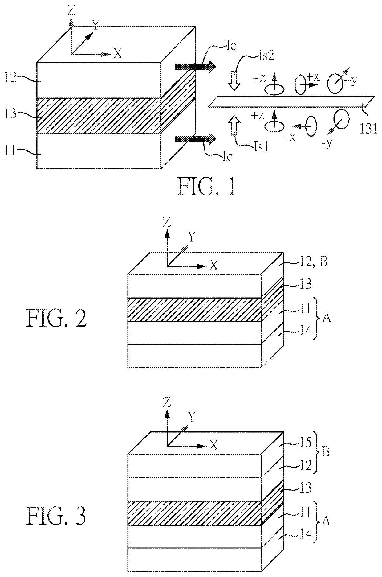
[0027]FIG. 1 is a perspective view of an electrically controlled nanomagnet of the present embodiment.

[0028]The electrically controlled nanomagnet of the present embodiment comprises: a first spin-Hall material layer 11 comprising a first spin-Hall material; a second spin-Hall material layer 12 comprising a second spin-Hall material; and a first magnetic layer 13 disposed between the first spin-Hall material layer 11 and the second spin-Hall material layer 12, wherein the first spin-Hall material and the second spin-Hall material are substantially mirror image to each other. In the present embodiment, the first spin-Hall material and the second spin-Hall material are respectively a spin-Hall material capable of generating perpendicular spin orbit torque (p-SOT).

[0029]As shown in FIG. 1, the nanomagnet of the present embodiment has a sandwiched structure comprising spin-Hall / magnetic / spin-Hall materials. The key criteria for enhancing the p-SOT and suppressing the in-plane SOT is tha...

embodiment 2

[0035]FIG. 2 is a perspective view of an electrically controlled nanomagnet of the present embodiment. The nanomagnet of the present embodiment is similar to that of Embodiment 1, except that the nanomagnet of the present embodiment further comprises a third spin-Hall material layer 14, wherein the first spin-Hall material layer 11 locates between the first magnetic layer 13 and the third spin-Hall material layer 14, and the third spin-Hall material layer 14 comprises a third spin-Hall material. Herein, the third spin-Hall material is a spin-Hall material capable of generating perpendicular spin orbit torque (p-SOT). Examples of the third spin-Hall material may comprise WTe2, MoTe2, or other spin-Hall material.

[0036]In the present embodiment, one spin-Hall material layer (i.e. the second spin-Hall material layer 12) is disposed on the top of the first magnetic layer 13 and two spin-Hall material layers (i.e. the first spin-Hall material layer 11 and the third spin-Hall material laye...

embodiment 3

[0037]FIG. 3 is a perspective view of an electrically controlled nanomagnet of the present embodiment. The nanomagnet of the present embodiment is similar to that of Embodiment 2, except that the nanomagnet of the present embodiment further comprises a fourth spin-Hall material layer 15, wherein the second spin-Hall material layer 12 locates between the first magnetic layer 13 and the fourth spin-Hall material layer 15, and the fourth spin-Hall material layer 15 comprises a fourth spin-Hall material. Herein, the fourth spin-Hall material is a spin-Hall material capable of generating perpendicular spin orbit torque (p-SOT). Examples of the fourth spin-Hall material may comprise WTe2, MoTe2, or other spin-Hall material.

[0038]In the present embodiment, two spin-Hall material layers (i.e. the second spin-Hall material layer 12 and the fourth spin-Hall material layer 15) are disposed on the top of the first magnetic layer 13 and another two spin-Hall material layers (i.e. the first spin-...


PUM

PropertyMeasurementUnit
spin-Hallaaaaaaaaaa
magneticaaaaaaaaaa
spin orbit torqueaaaaaaaaaa

Abstract

An electrically controlled nanomagnet and a spin orbit torque magnetic random access memory (SOT-MRAM) including the same are provided. The electrically controlled nanomagnet includes: a first spin-Hall material layer including a first spin-Hall material; a second spin-Hall material layer including a second spin-Hall material; and a first magnetic layer disposed between the first spin-Hall material layer and the second spin-Hall material layer, wherein the first spin-Hall material and the second spin-Hall material are substantially mirror image to each other.

Description

CROSS REFERENCE TO RELATED APPLICATION[0001]This application claims the benefit of filing date of U.S. Provisional Application Ser. No. 62 / 785,299 entitled “Spin-Hall / magnetic / Spin-Hall sandwiched structure for perpendicular spin-orbit-torque and its applications on switching perpendicular magnetoresistive random access memory” filed Dec. 27, 2018 under 35 USC § 119(e)(1).BACKGROUND1. Field[0002]The present disclosure relates to an electrically controlled nanomagnet and a spin orbit torque magnetic random access memory comprising the same.2. Description of Related Art[0003]Spin-transfer-torque (STT) based Magnetoresistive random access memory (MRAM) is a promising candidate for non-volatile, fast, and high endurance memory. However, the limited conversion efficiency from charge to spin current makes it difficult to scale down the critical current for ˜ns fast switching. On the other hand, spin-orbit torque (SOT) switching shows promise for overcoming such limitation. The efficacy of...

Claims


Application Information

Patent Timeline
Patent Type & Authority Patents(United States)
IPC IPC(8): H01L43/04H01L43/06H01L27/22
CPCH01L43/04H01L27/222H01L43/06H10B61/00H10N52/80H10N50/85H10N50/80H10N50/10H10N52/00
Inventor LIN, HSINWU, SHIH-YUHSU, CHUANG-HAN
Owner ACAD SINIC
Why Eureka
Try Eureka