
Polymer composite containing quantum dots

a polymer composite and quantum dots technology, applied in the direction of luminescent compositions, coatings, chemistry apparatuses and processes, etc., can solve the problems of not revealing the compositions described herein, qd is very susceptible to photo-oxidation, and moisture can have similar effects

Active Publication Date: 2021-04-20
ROHM & HAAS ELECTRONICS MATERIALS LLC
View PDF6 Cites 0 Cited by
  • Summary
  • Abstract
  • Description
  • Claims
  • Application Information

AI Technical Summary

Benefits of technology

The present invention provides a polymer composite that includes quantum dots. The composite includes a polymerized mixture of at least two compounds: a first compound with at least one vinyl group and a molecular weight of 300 to 2000, and a second compound with at least one vinyl group and a molecular weight of 100 to 750. The quantum dots are dispersed throughout the polymer composite, resulting in improved performance and durability. The technical effect of this polymer composite is improved performance and durability.

Problems solved by technology

Unfortunately, QD are very susceptible to photo-oxidation during light absorption / conversion process.
Also, moisture can have similar impacts when ligands are not compatible.
However, this reference does not disclose the compositions described herein.

Method used


Image

  • Polymer composite containing quantum dots
  • Polymer composite containing quantum dots

Examples


example 1

[1] Sample Preparation for Examples

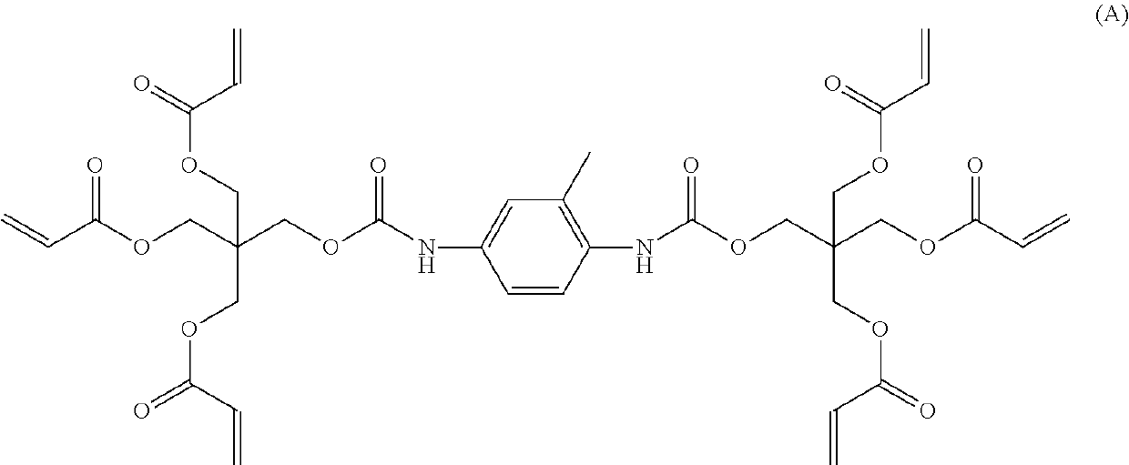
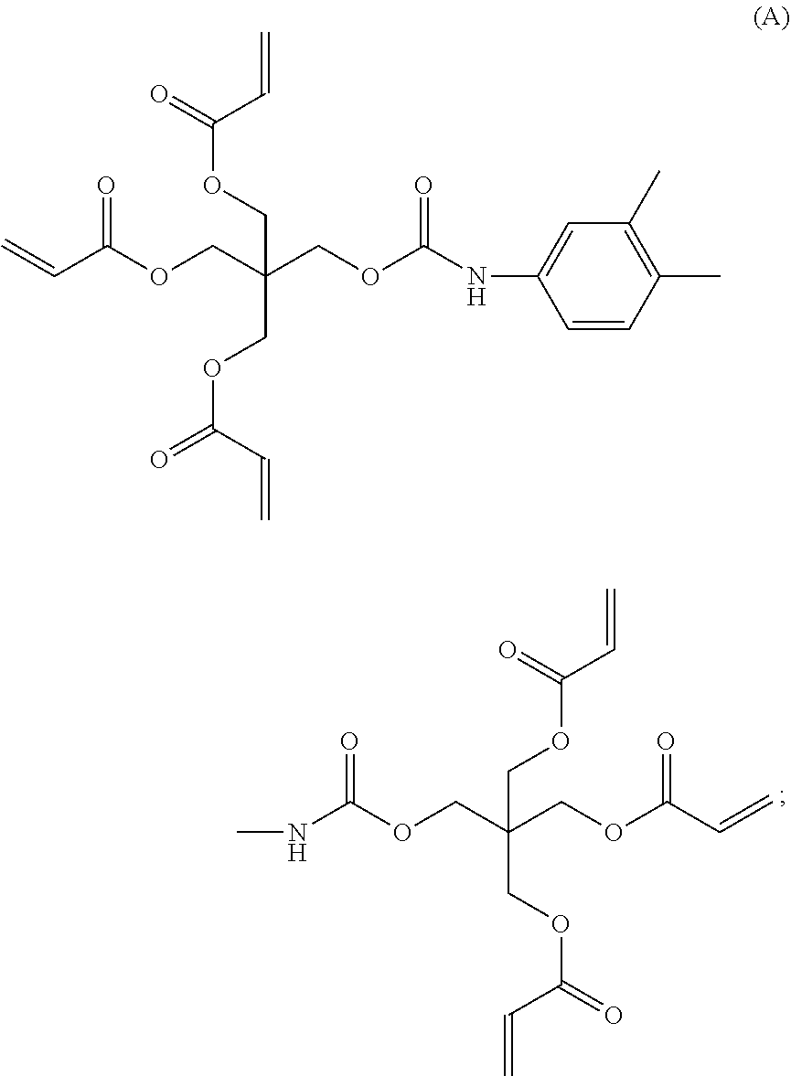
[0026]All samples were prepared by lamination of the resin formulations between two i-Component PET barrier films. Approximately 2 mL of resin was dispensed on the bottom film and the top has applied with a gap coating bar with gap setup (10 mil-12 mil) based on desired film thickness. Samples were cured using a FUSION UV SYSTEMS, INC (DRS-10 / 12 QNH), 500 mJ / cm{circumflex over ( )}2 UV curing intensity.

Formulation Information

1. Blend SR833 and photoinitiator together.

2. Mix PHS-GMA with SR833. Heat it to 50 C for 15 mins.

3. Add IBOA with QD into the mixture.

4. Cure film under UV light

[2] Formulation

[0027]

Wt %PHS-GMAPHSGreen CFQD QDIBOASR833I-819#11000.59.578.51.5#22000.59.568.51.5#30100.59.578.51.5#40200.59.568.51.5

[3] Morphology Characterization

[0028]Transmission electron microscopy (TEM) shows QD has large agglomeration in SR833 rich resin which proves that it has poor compatibility with SR833. With PHS, QD has better dispersion, but they are con...

example 2

[1] Sample Preparation for Examples

[0034]All samples were prepared by lamination of the resin formulations between two i-Component PET barrier films. Approximately 2 mL of resin was dispensed on the bottom film and the top has applied with a gap coating bar with gap setup (10 mil-12 mil) based on desired film thickness. Samples were cured in a Fusion UV F300S curing system with UVA 800 mJ / cm, unless otherwise noted. Film thicknesses were determined by measurement of the cured films with a micrometer and then subtracting out the barrier film thickness. Photoluminescent Quantum Yield (PLQY), peak emission wavelength (PWL) and full-width half-max of the emission peak (FWHM) were measured with a custom integrating sphere with 450 nm excitation LED or Hamamatsu C9920-02G integrating sphere. In case of BLU spectrum measurement, the cured film was placed between the light guide plate and prism film / brightness enhancement film of blue LED based backlight unit (BLU). BLU spectrum was measure...


PUM

PropertyMeasurementUnit
temperatureaaaaaaaaaa
thicknessaaaaaaaaaa
thicknessaaaaaaaaaa

Abstract

A polymer composite comprising quantum dots; said polymer composite comprising: (a) quantum dots; (b) polymerized units of a first compound having at least one readily polymerizable vinyl group, a molecular weight from 300 to 20,000 and at least one continuous acyclic hydrocarbyl chain of at least five carbon atoms; and (c) polymerized units of a second compound having at least one readily polymerizable vinyl group and a molecular weight from 100 to 750; wherein a readily polymerizable vinyl group is part of a (meth)acrylate ester group or is attached directly to an aromatic ring, and the molecular weight of the first compound minus the molecular weight of the second compound is at least 100.

Description

FIELD OF THE INVENTION[0001]The present invention relates to a polymer composite containing quantum dots.BACKGROUND OF THE INVENTION[0002]Semiconductor quantum dots (QD) provide optical absorption and emission (photoluminescence PL or electroluminescence EL) behaviors that are significantly different from those of bulk materials. As the particle size decreases, effective energy bandgap (Eg), or available energy levels, increases and creates a blue shifted PL spectrum. This spectrum tunability by the particle size dependent quantum confinement effect within the same material is a critical advantage over conventional bulk semiconductors. Because of their unique optical properties, QD have been of great interest in many display and lighting applications. Most QD have inorganic shells with a larger bandgap material to confine electron and hole pairs within the core region and prevent any surface charge states. The outer shells are then capped by organic ligands to reduce trap states of ...

Claims


Application Information

Patent Timeline
Patent Type & Authority Patents(United States)
IPC IPC(8): C09K11/02C08F222/10C09D133/12C09K11/08C08K3/013
CPCC09K11/02C08F222/1006C08K3/013C09D133/12C09K11/08C08F222/102C08F2800/20C08K3/10C08F220/1811C08F220/283B82Y30/00B82Y20/00
Inventor HUANG, JESSICA YEBAI, ZHIFENGCHEN, LIANGJOO, JAKEHU, ING-FENGTAYLOR, JAMES C.
Owner ROHM & HAAS ELECTRONICS MATERIALS LLC
Learn More