Reversing valve for hydraulic piston pump

a technology of hydraulic piston pump and reverse valve, which is applied in the direction of piston pump, positive displacement liquid engine, borehole/well accessories, etc., can solve the problems of large workload of surface treatment of power fluid, large workload of moving parts, and high leakage of sliding sleeve valve, so as to save energy consumption and eliminate complex equipment

Active Publication Date: 2021-05-04
CUI NAILIN
View PDF14 Cites 0 Cited by
  • Summary
  • Abstract
  • Description
  • Claims
  • Application Information

AI Technical Summary

Benefits of technology

[0005]A primary object of the present invention is to provide a reversing valve for a hydraulic piston pump. The hydraulic piston pump designed with the reversing valve can use pure water or high water content produced liquid as the power fluid, thereby eliminating the complex equipment on the surface for handling the power fluid and saving the energy consumption in the process of treatment.
[0006]Another object of the present invention is to provide a reversing valve for a hydraulic piston pump. The hydraulic piston pump designed with the reversing valve can work at a very low pump stroke, thereby greatly improving the reliability of the pump and increasing the working life of the pump.
[0007]Yet another object of the present invention is to provide a reversing valve for a hydraulic piston pump. The hydraulic piston pump designed with the reversing valve has a small leakage, thereby significantly improving efficiency and reducing energy consumption.
[0008]Still yet another object of the present invention is to provide a hydraulic piston pump reversing valve which its manufacturing cost is significantly lower than that of a sliding sleeve reversing valve.
[0015]During reversing, the reversing valve of the hydraulic piston pump of the present invention eliminates or reduces the vibration and impact of the main valve by providing the damper hole on the main valve core, so that it can smoothly reverse under different operating conditions, thereby extending the service life of the reversing valve. Because the reversing valve adopts the structure of two two-position three-way cone valves, the valve seats and valve cores are linearly sealed, and eliminating leakage during working, and the valve core will not be stuck due to impure power fluid. The reversing valve no longer needs the power fluid with good lubricity, high cleanliness and proper viscosity, and pure water or fluid with high water content and low viscosity can be directly used as power fluid. Another advantage is that the reversing valve can be realized low pump stroke (less than 3 times per minute). This greatly reduces the moving speed of the moving members to reduce the abrasion, and increases the service life of the whole system several times. The above-mentioned advantages can not be achieved by the existing sliding sleeve reversing valve of hydraulic piston pump.

Problems solved by technology

Firstly, since the sliding sleeve reversing valve cannot achieve low pump stroke reversing, the power fluids are required to have good lubricity to reduce the abrasion of moving members.
Thirdly, since members of the sliding sleeve reversing valve is in clearance fit, the power fluids are required to have an appropriate viscosity; If water and other low viscous fluids are used as power fluid, not only the moving parts will wear rapidly but also the leakage of sliding sleeve valve will be very serious.
However, after the water cut of oil wells increased, the workload of surface treatment of power fluid was too large, the production cost was too high.

Method used


Image

  • Reversing valve for hydraulic piston pump
  • Reversing valve for hydraulic piston pump
  • Reversing valve for hydraulic piston pump

Examples


Embodiment Construction

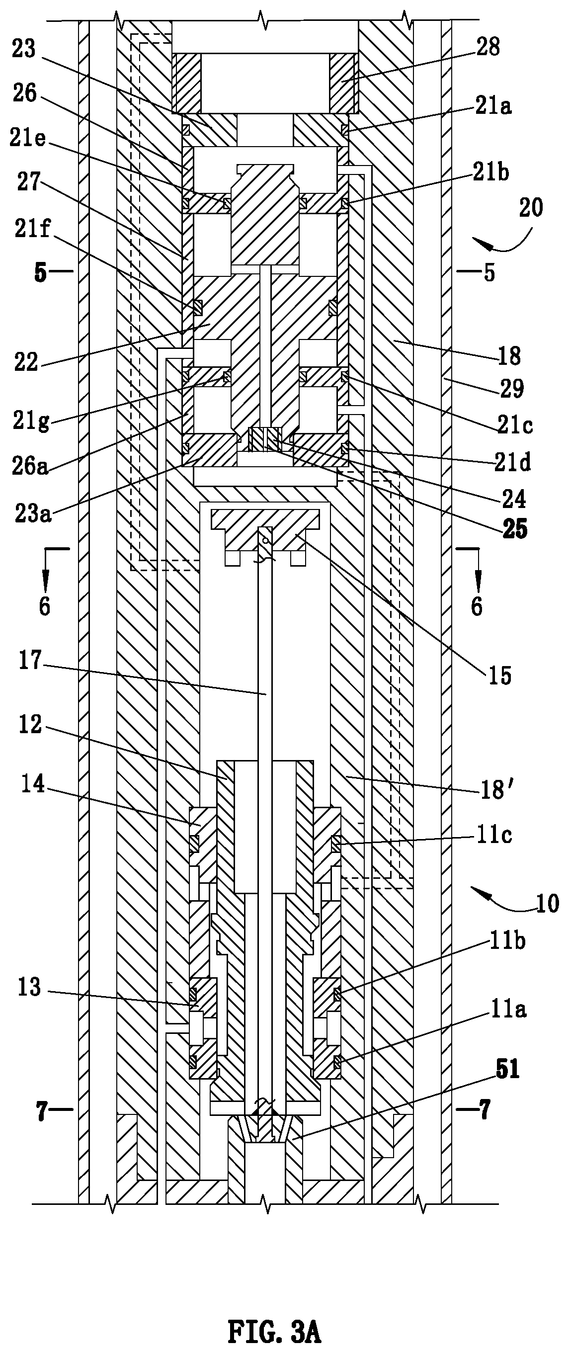
[0031]As for FIG. 3A and FIG. 3B, it needs to be explained that FIG. 3A and FIG. 3B are exactly the same in view. The difference is that each number on FIG. 3A represents the components of the reversing valve, and each number on FIG. 3B represents the chambers, connecting ports and flow passages of the reversing valve.

[0032]As shown in FIGS. 3A and 8, a first sealing line 13a is formed at a junction between a lower end face and an inner surface of the pilot valve seat 13 and a second sealing line 13b is formed between an upper end face of the pilot valve seat 13 and its inner surface, and a first conical surface 12a and a second conical surface 12c are arranged on the hollow valve core 12. There is a first cylinder 12b above the first conical surface 12a, a second cylinder 12d below the second conical surface 12c. A convex cylinder 12e is provided above the second conical surface 12c, and a sealing cylinder 12f is arranged above the convex cylinder 12e. The pilot valve 10 also inclu...


PUM


Abstract

A reversing valve for a hydraulic piston pump, including a pilot valve and a main valve. The pilot valve includes a pilot valve seat, a hollow valve core and a pull rod. The main valve comprises an upper valve seat, a lower valve seat and a main valve core. When the hollow valve core is at a upper position, the control flow passage communicates with the spent fluid flow passage, and the main valve core is at a lower position, so the power piston is driven to move downwardly by the power fluids provided by the main valve. When the hollow valve core is at a lower position, the power fluid controls the main valve core to be seated at the upper position, and the power piston is driven to move upwardly by the power fluids provided by the pilot valve.

Description

CROSS-REFERENCE TO RELATED APPLICATIONS[0001]This application is a continuation of International Application No. PCT / CN2018 / 000217 with a filling date of Jun. 7, 2018, designating the United states, now pending, and further claims to the benefit of priority from Chinese Application No. 201710683380.7 with a filing date of Aug. 4, 2017. The content of the aforementioned applications, including any intervening amendments thereto, are incorporated herein by reference.TECHNICAL FIELD[0002]The present application relates to a hydraulic piston pump for extracting oil from wells, and more particularly to a reversing valve for controlling the reciprocating motion of the hydraulic piston pump.BACKGROUND OF THE INVENTION[0003]For existing hydraulic piston pumps, high-pressure power fluids are injected into oil wells by surface pumps, and sliding sleeve reversing valves in the wells control the reciprocating motion of pistons at power ends, thereby driving the piston of the pump to reciprocate...

Claims


Application Information

Patent Timeline
Patent Type & Authority Patents(United States)
IPC IPC(8): E21B34/14E21B43/12F04B49/22
CPCE21B34/14E21B43/121F04B49/22E21B2200/06F04B9/103F04B49/225F04B53/10F04B9/1095F04B47/08E21B43/126
Inventor CUI, NAILIN
Owner CUI NAILIN
Why Eureka
Try Eureka