Heat exchanger tube

a heat exchanger and tube technology, applied in the direction of heat exchange apparatus, tubular elements, lighting and heating apparatus, etc., can solve the problems of increasing the cost of the entire system, reducing the production speed of tubes, and increasing the manufacturing cost. , to achieve the effect of increasing the driving temperature difference, reducing the risk of breakage and faster wear, and reducing the production cos

Active Publication Date: 2021-05-04
WIELAND WERKE AG
View PDF66 Cites 1 Cited by
  • Summary
  • Abstract
  • Description
  • Claims
  • Application Information

AI Technical Summary

Benefits of technology

[0019]In order to permit the heat transfer between the medium which outputs heat and the evaporating substance, the temperature of the medium which outputs heat must be higher than the saturation temperature of the substance. This temperature difference is referred to as the driving temperature difference. The higher the driving temperature difference, the more heat can be transferred. On the other hand, the aim is mostly to keep the driving temperature difference low, since this is advantageous for the process efficiency.
[0020]The cavities according to the invention make the process of the nucleate boiling more intensive in order to increase the heat transfer coefficients during the evaporation. The formation of bubbles starts at nuclei. These nuclei are usually small pockets of gas or vapor. When the growing bubble has reached a certain size, it becomes detached from the surface. If the nucleus is flooded with fluid in the course of the detachment of the bubble, the nucleus is deactivated. The surface must therefore be conf

Problems solved by technology

Moreover, the necessary filling quantity of refrigerant drops, which can make up a considerable portion of the cost of the entire system with the chlorine-free safety refrigerants which are predominantly used nowadays.

Method used


Image

  • Heat exchanger tube
  • Heat exchanger tube
  • Heat exchanger tube

Examples


Embodiment Construction

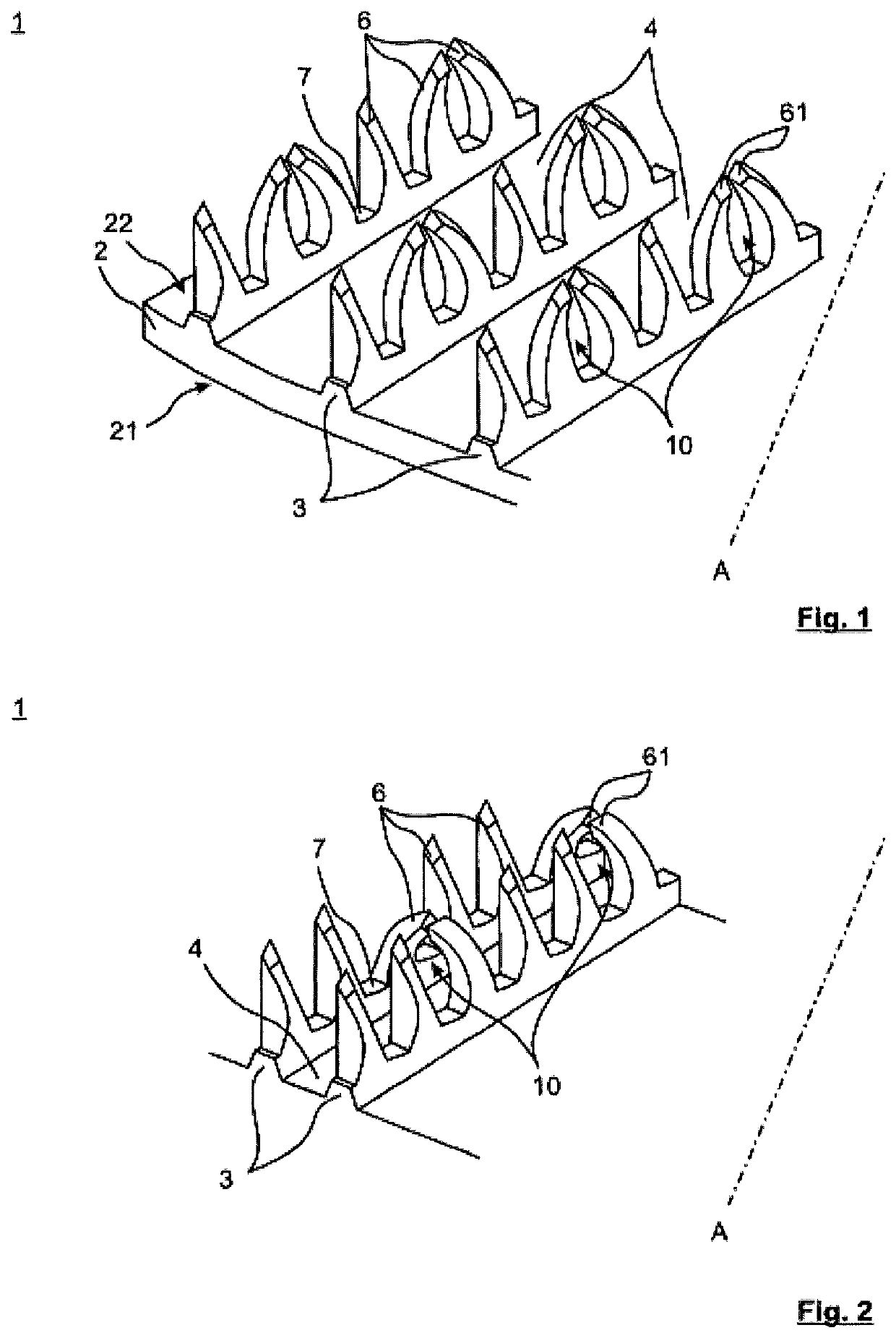
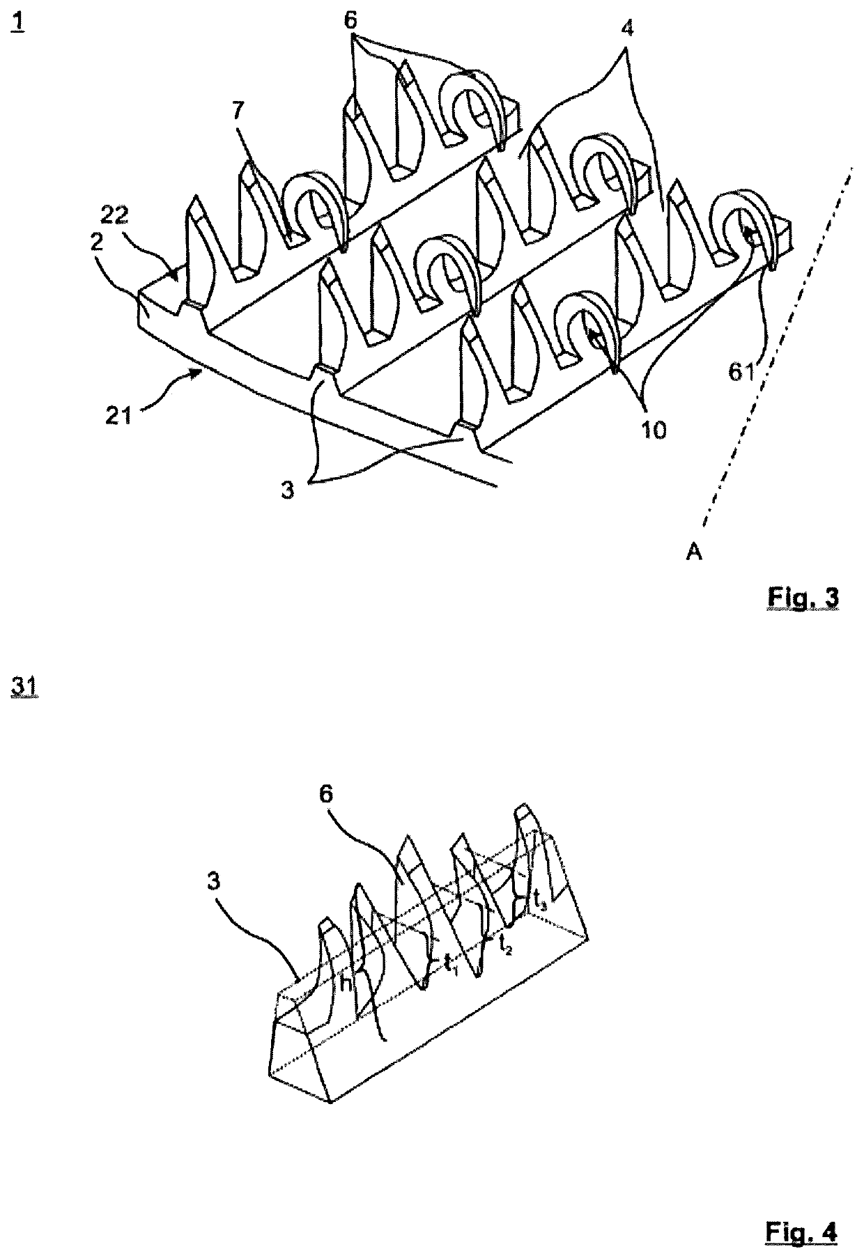
[0043]FIG. 1 is a schematic, oblique view of a tube detail of the heat exchanger tube 1 with an inventive structure on the inner tube face 22. The heat exchanger tube 1 has a tube wall 2, an outer tube face 21 and an inner tube face 22. Helically circumferential continuous fins 3 are formed from the tube wall 2 on the inner tube face 22. The longitudinal tube axis A runs at a certain angle with respect to the fins 3. Continuously extending primary grooves 4 are formed between respectively adjacent fins 3.

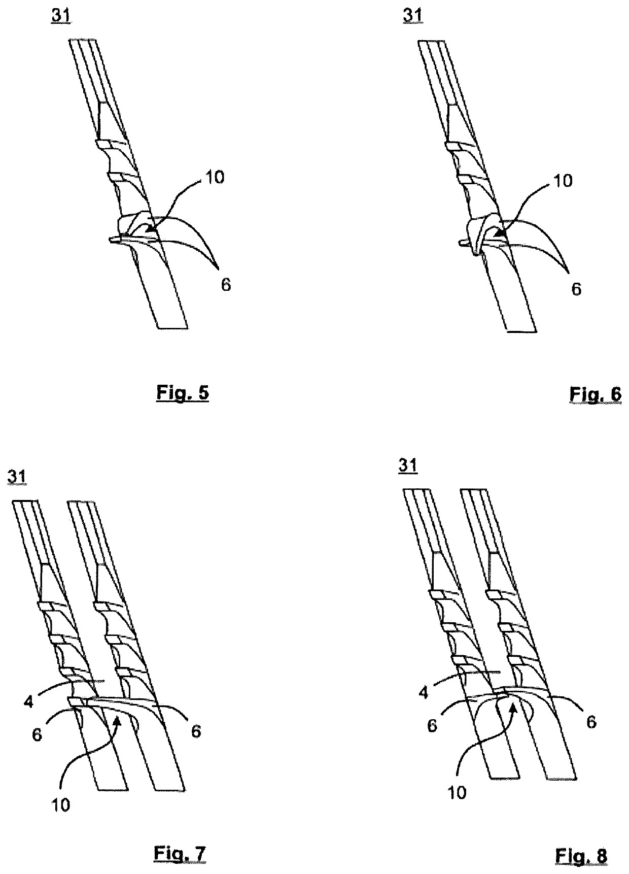
[0044]A plurality of projections 6 are shaped with respect to one another in pairs in such a way that cavities 10 are formed between adjacent projections 6. In this context, the tips 61 of at least two projections 6 are in contact with one another along the fin profile.

[0045]The projections 6 are formed between primary grooves 4 by cutting the fins 3 at a cutting depth transversely with respect to the fin profile to form fin layers and by raising the fin layers in a main orientation...


PUM


Abstract

The invention relates to a heat exchanger tube having a tube longitudinal axis, wherein fins extend continuously from the tube wall on the tube outer face and/or the tube inner face, or extend axially parallel thereto or in the form of a helix. Continuously extending primary grooves are formed between adjacent fins, said fins have at least one structured area on the tube outer face and/or tube inner face, and the structured area has a plurality of projections of a projection height projecting from the surface, the projections being separated by notches. According to the invention, a plurality of projections are deformed relative one another in pairs to such an extent that cavities are formed between adjacent projections. Furthermore, according to the invention, a plurality of projections are deformed in the direction of the tube wall such that cavities are formed between a respective projection and the tube wall.

Description

TECHNICAL FIELD[0001]The invention relates to a metallic heat exchanger tube having a longitudinal tube axis with a tube wall, an outer tube face, an inner tube face, axially parallel or helically circumferential continuous fins formed from the tube wall on the outer tube face and / or inner tube face, continuously extending primary grooves formed between respectively adjacent fins, the fins having at least one structured region on the outer tube face and / or inner tube face, the structured region having a multiplicity of projections separated by notch formations.BACKGROUND AND SUMMARY[0002]Such metallic heat exchanger tubes serve, in particular, for evaporating fluids from pure substances or mixtures on the outer tube face.[0003]Evaporation occurs in many fields of refrigeration and air-conditioning technology as well as in processing and energy technology. Tubular bundle heat exchangers in which fluids evaporate from pure materials or mixtures on the outer tube face and in the proces...

Claims


Application Information

Patent Timeline
IPC IPC(8): F28F1/14F28F1/18F28F1/40F28F1/42F28F1/36
CPCF28F1/18F28F1/36F28F1/40F28F1/422
Inventor GOTTERBARM, ACHIMLUTZ, RONALDEL HAJAL, JEANKNAB, MANFRED
Owner WIELAND WERKE AG
Why Eureka
Try Eureka