Laser target pointer

a laser and target technology, applied in the field of laser target pointers, can solve the problems of inconvenient operation of functional buttons and switches, limited illumination distance or range of invisible light, and complicated adjustment mechanism of laser alignment, etc., and achieves the effects of simple structure, easy assembly and easy adjustmen

Active Publication Date: 2021-05-18
QUARTON
View PDF10 Cites 6 Cited by
  • Summary
  • Abstract
  • Description
  • Claims
  • Application Information

AI Technical Summary

Benefits of technology

[0003]Accordingly, it is the primary objective of the present invention to provide a laser target pointer for a gun, which comprises an adjustment mechanism equipped with a biaxial pivoting mechanism to adjust the position of the laser aiming point of the laser module; in addition, the biaxial pivoting mechanism has the advantages of simple structure, easy assembly, and easy adjustment.
[0004]Another objective of the present invention is to provide a laser target pointer for a gun, which comprises a magnetic switch with connecting cable. It can be magnetically attracted and detachably connected with a contact block provided on the laser target pointer and then electrically connected to the laser target pointer. The power of the laser target pointer can be conveniently turned on or off by operating the magnetic switch with connecting cable.
[0006]Yet another objective of the present invention is to provide a laser target pointer for a gun, which comprises a plurality of luminous patterns. Each of the patterns corresponds to at least one operation function. By pressing the operation buttons of the laser target pointer, one or some of the plurality of patterns can emit light of a predetermined color, such that the user can clearly and quickly identify which one of the operation functions of the laser target pointer is currently enabled. Wherein, at least one of the patterns can emit at least two different colors of light, such that a single pattern can be used to identify at least two different operation functions.
[0007]In order to achieve the aforementioned objectives, the present invention provides a laser target pointer which comprises: a case, a lighting module, a laser module, a power module, an operating module and an adjustment mechanism. The lighting module is located in the case and comprises at least one light emitting element for emitting illumination light forwardly out from the case. The laser module is located inside the case and comprises at least one laser unit for emitting laser beam forwardly out from the case. The power module is located inside the case and is electrically connected to the lighting module and the laser module to provide electric power to the at least one light emitting element and the at least one laser unit. The operating module is electrically connected to the power module and comprises at least one button which can be pressed by a user in order to operate the laser target pointer. The adjustment mechanism is connected with the laser module for adjusting a position of a laser aiming point of a laser beam emitted by the at least one laser unit of the laser module. The adjustment mechanism comprises a biaxial pivoting mechanism, a first adjusting screw set and a second adjusting screw set. Wherein, a side surface of the laser module is pivotally coupled to the biaxial pivoting mechanism, such that the laser module can use the biaxial pivoting mechanism as a pivot to perform biaxial pivoting movements according to a first axis and a second axis. Wherein, the first adjusting screw set is disposed on the side surface of the laser module in such a manner that, by rotating the first adjusting screw set, the side surface of the laser module will be pushed by the first adjusting screw set to rotate around the first axis using the biaxial pivoting mechanism as the pivot; in addition, the second adjusting screw set is disposed on a bottom surface of the laser module in such a manner that, by rotating the second adjusting screw set, the bottom surface of the laser module will be pushed by the second adjusting screw set to rotate around the second axis using the biaxial pivoting mechanism as the pivot. Wherein, by rotating the first adjusting screw set and the second adjusting screw set, the laser module can perform biaxial pivoting movements using the biaxial pivoting mechanism as the pivot, so as to adjust the position of the laser aiming point of the laser beam emitted by the at least one laser unit.
[0008]In a preferred embodiment, the biaxial pivoting mechanism comprises a fixed axis and a sleeve axis; the fixed axis extends along a first direction and is fixed to the case; the sleeve axis has a through hole extending in the first direction and a shaft portion extending in a second direction, wherein the second direction is perpendicular to the first direction; the through hole of the sleeve axis is sleeved on the fixed axis in a pivotable manner, so that the sleeve axis can perform pivoting movements around the first axis about the fixed axis; the side surface of the laser module is pivotally coupled to the shaft portion of the sleeve axis, so that the laser module can perform the pivoting movements around the second axis about the shaft portion of the sleeve axis. Wherein, the first adjusting screw set comprises a first screw and a first pushing block; by rotating the first screw, the first pushing block can be driven to push the side surface of the laser module in order to cause the laser module together with the sleeve axis to pivot around the first axis by using the fixed axis as the pivot. Wherein, the second adjusting screw set comprises a second screw and a second pushing block; by rotating the second screw, the second pushing block can be driven to push the bottom surface of the laser module in order to cause the laser module to pivot around the second axis by using the shaft portion of the sleeve axis as the pivot. Wherein, the adjustment mechanism further comprises at least one position retaining element for providing an elastic pushing force to the laser module, so that, when the first screw and the second screw stop rotating, the position of the laser module can be maintained by the elastic pushing force of the at least one position retaining element.
[0009]In a preferred embodiment, a flat bottom groove extending along the first direction is formed on the side surface of the laser module, in addition, the first pushing block has a square shape with a width substantially matching the width of the flat bottom groove; the first pushing block is located in the flat bottom groove and abuts against the flat bottom groove; the position retaining element is a conical coil spring which abuts the laser module and the case for providing the elastic pushing force to laser module, so that the first pushing block and the second pushing block can keep pressing against the laser module.

Problems solved by technology

However, existing laser target pointers still have many structural shortcomings, such like: the adjustment mechanism of laser alignment is complicated, the operation of functional buttons and switches is inconvenient, the illumination distance or range of invisible light is limited, the visibility of the functional menu is not good, and etc.

Method used


Image

  • Laser target pointer
  • Laser target pointer
  • Laser target pointer

Examples


Embodiment Construction

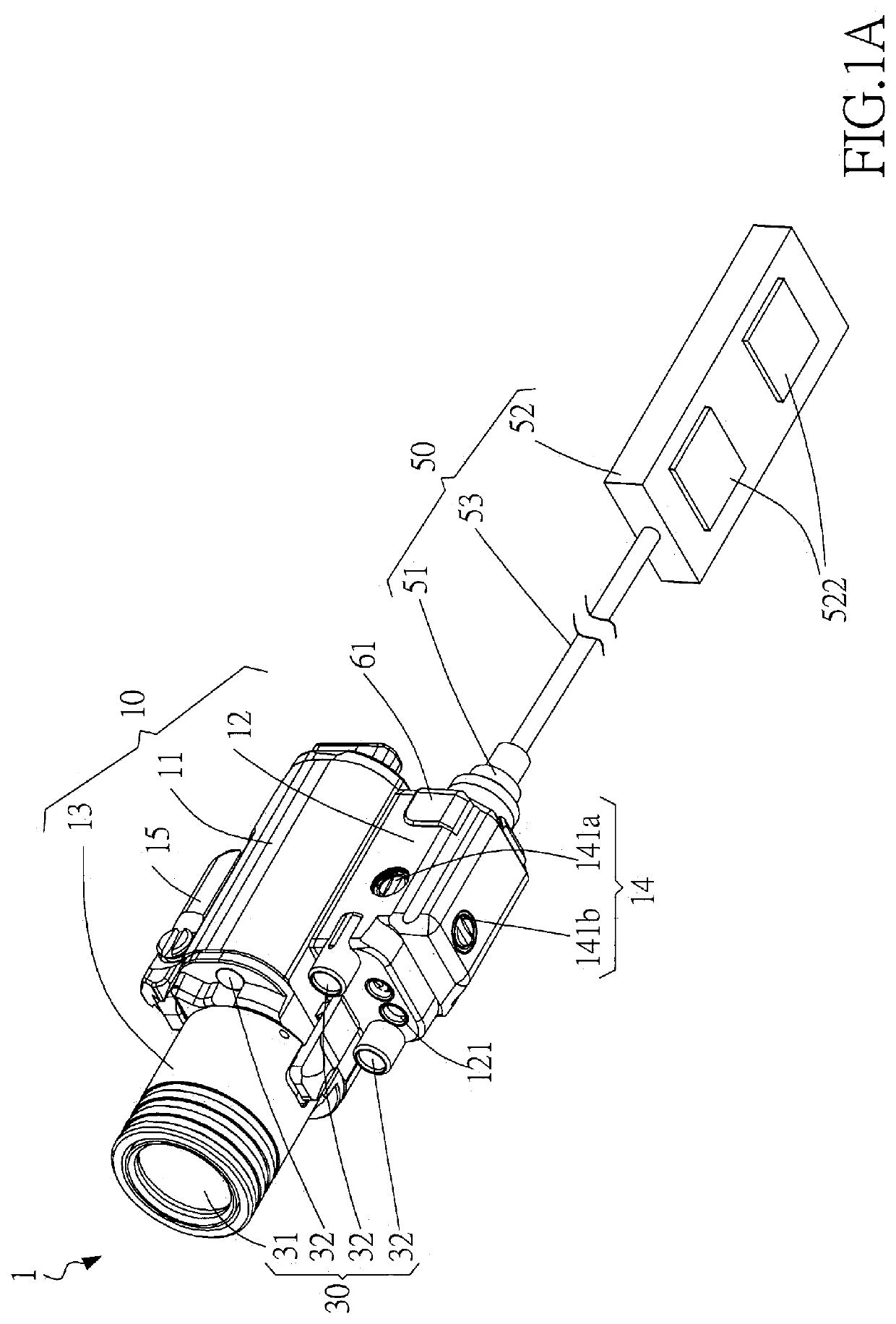
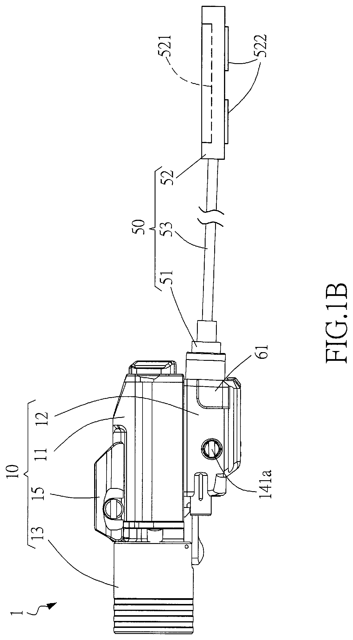
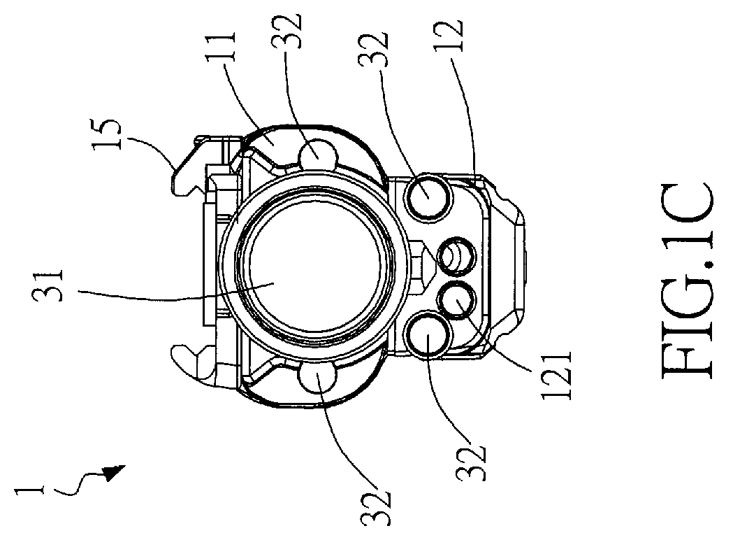
[0026]The present invention discloses a laser target pointer for a gun, which comprises a case, a lighting module, a laser module, an operating module, an adjustment mechanism and a magnetic switch with connecting cable. The adjustment mechanism equipped with a biaxial pivoting mechanism to adjust the position of the laser aiming point of the laser module; in addition, the biaxial pivoting mechanism has the advantages of simple structure, easy assembly, and easy adjustment. The magnetic switch with connecting cable can be magnetically attracted and detachably connected with a contact block provided on the laser target pointer and then electrically connected to the laser target pointer. The power of the laser target pointer can be conveniently turned on or off by operating the magnetic switch with connecting cable. The lighting module comprises a plurality of invisible light emitting diodes; the divergence angles of the invisible illumination light emitted by the plurality of invisib...


PUM

PropertyMeasurementUnit
light divergence anglesaaaaaaaaaa

Abstract

A laser target pointer comprises a case, a lighting module, a laser module, an operating module, an adjustment mechanism and a magnetic switch. The adjustment mechanism is equipped with a biaxial pivoting mechanism to adjust the position of the laser aiming point of the laser module. The magnetic switch can be magnetically attracted and detachably connected with a contact block and electrically connected to the laser target pointer. The power of the laser target pointer can be conveniently turned on or off by operating the magnetic switch. The lighting module comprises a plurality of invisible light emitting diodes having different divergence angles in order to provide different irradiation distances. The operating module comprises a plurality of luminous patterns each corresponding to an operation function, such that the user can clearly and quickly identify which one of the operation functions is currently enabled.

Description

BACKGROUND OF INVENTION1. Field of the Invention[0001]The invention relates to a laser target pointer, and more particularly to the laser target pointer that can be assembled onto a gun so as to provide an auxiliary aiming function to a gun shooting path of the gun.2. Description of the Prior Art[0002]Except as a weapon that accelerates a bullet by exploding gunpowder thereinside, the gun can be particularly structured for recreations and / or games (a paintball gun or an air gun, for example), and can be, but not limited to, pneumatically powered by a compressed air bottle. In order to raise the shooting accuracy, gun manufacturers have developed versatile laser target pointers individually equipped onto a gun body of the gun for emitting a laser beam to demonstrate a corresponding shooting path and direction, such that an auxiliary aiming function can be provided. However, existing laser target pointers still have many structural shortcomings, such like: the adjustment mechanism of ...

Claims


Application Information

Patent Timeline
Patent Type & Authority Patents(United States)
IPC IPC(8): F41G1/35F21V21/30F21S9/02F21V21/096F21V23/04G02B23/16F21Y115/30F21Y115/10
CPCF41G1/35F21S9/02F21V21/096F21V21/30F21V23/04G02B23/16F21Y2115/10F21Y2115/30
Inventor HUANG, CHAO CHICHEN, LIANG CHIANG
Owner QUARTON
Why Eureka
Try Eureka