Medical device for detecting at least one analyte in a body fluid

a technology of a medical device and a body fluid, which is applied in the field of medical devices for detecting at least one analyte in a body fluid, can solve the problems of increasing the volume of the system, significant technical challenges, and increasing the production cost of the analytical system, and achieves the effect of small construction volume and robust design

Active Publication Date: 2021-05-25
ROCHE DIABETES CARE INC
View PDF7 Cites 0 Cited by
  • Summary
  • Abstract
  • Description
  • Claims
  • Application Information

AI Technical Summary

Benefits of technology

[0040]Specifically, the insertion cannula may have a shape which corresponds to a shape of the analyte sensor. Exemplarily, the analyte sensor may have a rectangular shape such as a rectangular cross-section perpendicular to a longitudinal axis of the analyte sensor and the insertion cannula may have a rectangular shape such as a rectangular cross-section perpendicular to a longitudinal axis of the insertion cannula, too. Thereby, the term “rectangular cross-section” may refer to a cross-section wherein the cross-section comprises two longitudinal sides and two narrow sides. The sides may be perpendicular to each other and the longitudinal sides may have a larger length than the narrow sides, respectively. However, small deviations may be feasible. The insertion cannula may be selected from the group consisting of: a closed cannula with the wall circumferentially enclosing a lumen of the insertion cannula; a slotted cannula, with the insertion cannula having a slot extending in an axial direction. Thereby, the term “axial direction” may refer to a direction situated in or on an axis of the insertion cannula. Specifically, the term axis direction may refer to a direction parallel to the longitudinal axis of the insertion cannula.
[0069]The opening of the insertion cannula compartment as well as the insertable portion of the analyte sensor may be shielded from external influences via the analyte sensor slider as described above or as will further be described below. The analyte sensor slider may exemplarily be fixedly attached to the housing of the medical device by at least one snap element such as by at least one kick-over spring. However, other embodiments may be feasible. Thus, the analyte sensor slider may seal the opening of the insertion cannula compartment. However, the sealing does not necessarily need to be a gas-tight sealing. A transfer of fluidic media such as gas and / or fluids between an exterior of the medical device and an interior of the medical device formed by the analyte sensor slider, the cover element and a part of the skin site exposed by the opening of the insertion cannula compartment may be allowable.
[0078]The proposed medical device, the method for assembling a medical device and the method of using a medical device provide many advantages over known devices and methods.
[0079]Usually, in common medical devices the user electrically contacts the electronics unit to the electrical contacts of the analyte sensor and seals the electrical contacts after inserting the analyte sensor. Therefore, common medical devices usually comprise sealing elements such as sealing rings and / or sealing lips. Further, common medical devices usually comprise contact elements such as contact pins or conductive rubbers for electrically contacting the electronics unit to the electrical contacts of the analyte sensor. Consequently, by applying common medical devices by the user or by the patient application errors may occur. Exemplarily, the user or the patient may not successfully tighten the medical device. Further, the sealing elements such as the sealing rings or the sealing lips may usually require high tolerance specifications. This may generally lead to high inspection costs. Moreover, the electronically contacting of the analyte sensor and the electronics unit may usually require high tolerance specifications such as concerning surface conditions, contact resistances, geometries and / or contact forces, too. Thus, this may also generally lead to high inspection costs. Further, common medical devices may usually require a large number of components. This may lead to a reduced wearing comfort for the user or the patient.
[0080]Therefore, the passive portion of the analyte sensor of the medical device according to the present invention may be elongated such that there is a thigh, electrical connection of the analyte sensor to the electronic unit and to the energy supply. The connection between the analyte sensor and the electronics unit may specifically be inseparable. Further, the connection may be testable during assembling the medical device. Beyond, no sensor connector may be required. Thus, only a small construction volume may be required. Further, a number of application errors may be diminished at least to a large extend. Moreover, the medical device according to the present invention may have a robust design.

Problems solved by technology

Despite the advantages implied by the above-mentioned known devices and methods, several technical challenges remain.
The electrical contact, however, in this case, typically has to be established by the user which in most cases does not have a medical training.
Thus, a significant technical challenge arises from the fact that these complex handling steps, typically performed by persons not having a medical training, have to be designed in a failsafe manner, in order to avoid technical malfunctions such as ingression of humidity into the analyte sensor system.
Further, the mechanical tolerances for the sealing devices as well as the tolerances for electrical contacts are rather strict, which typically raises the production costs for the analytical systems.
Additionally, typically, a large number of components are required which, in total, increase the volume of the system.
In increased weight and volume, however, decreases the convenience of wearing for the user.

Method used


Image

  • Medical device for detecting at least one analyte in a body fluid
  • Medical device for detecting at least one analyte in a body fluid
  • Medical device for detecting at least one analyte in a body fluid

Examples


Embodiment Construction

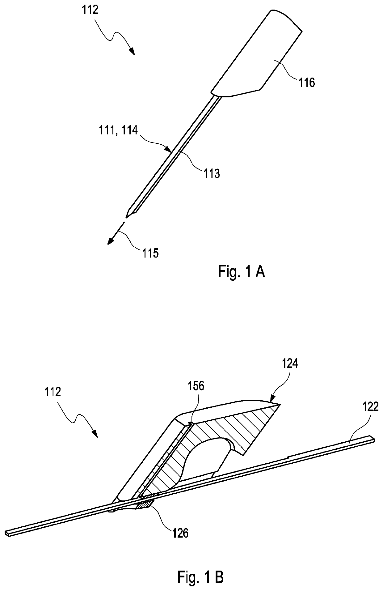
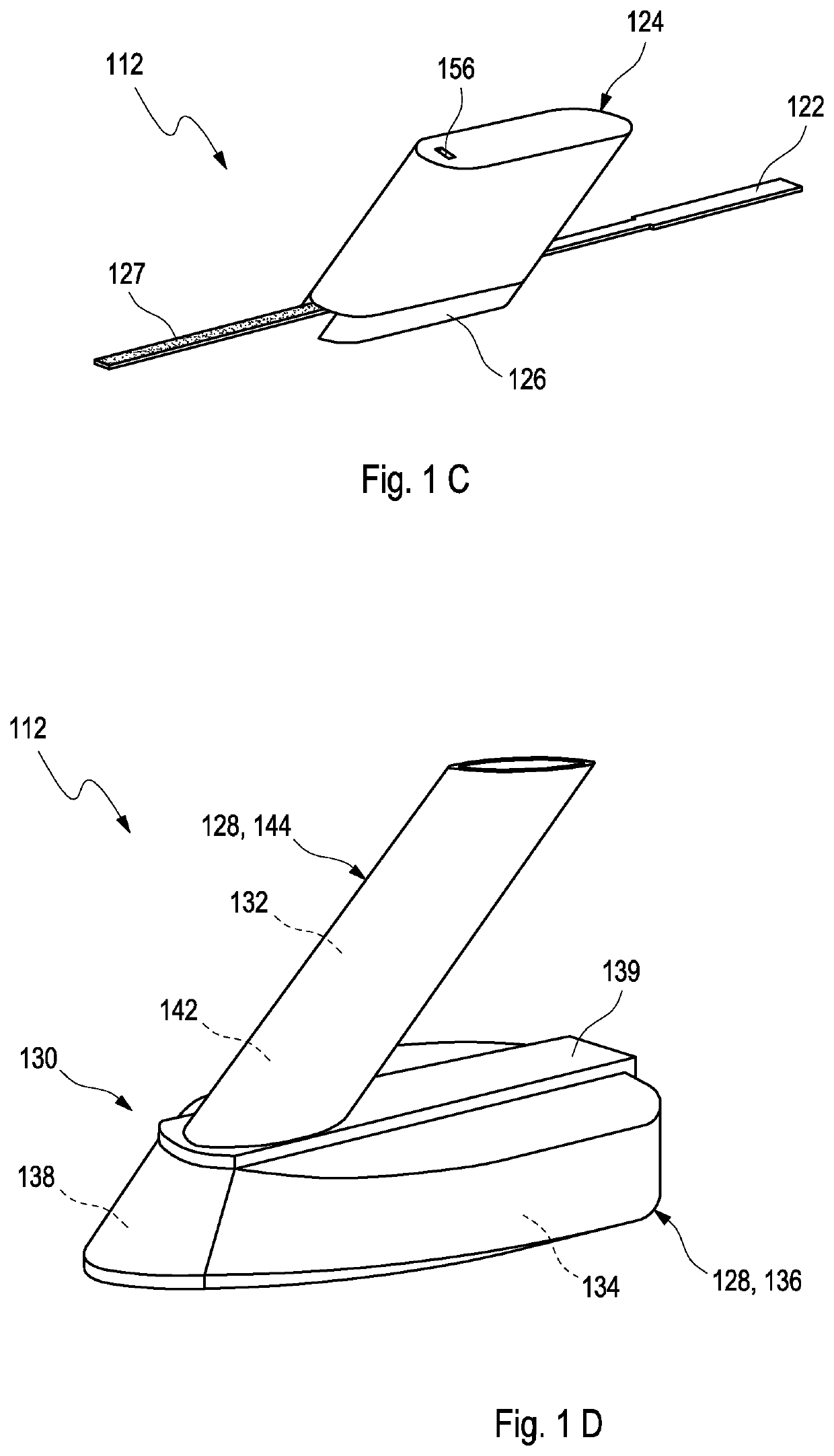
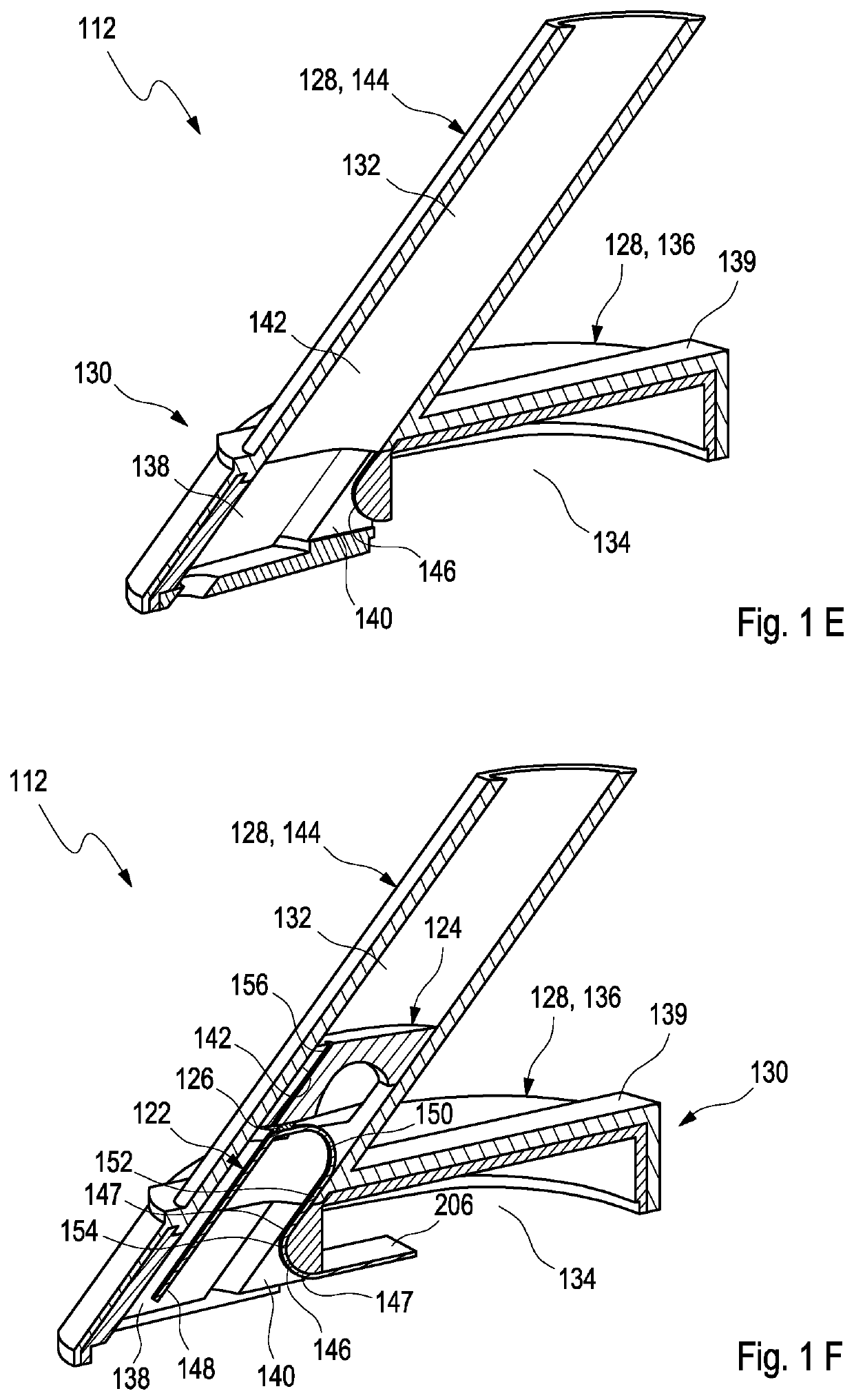
[0157]FIGS. 1A to 1M show an exemplary embodiment of a method for sampling a medical device 110. The medical device 110 is depicted in FIGS. 1K to 1M. In FIG. 1K, the medical device 110 is illustrated in a cross-section of view. In FIGS. 1L to 1M, the medical device 110 is illustrated in different perspective views, respectively. In FIGS. 1A to 1J, various intermediate products 112 of the medical device 110 are shown.

[0158]Firstly, as depicted in FIG. 1A, an insertion cannula 114 may be provided. The insertion cannula 114 may be fixedly attached to a insertion cannula slider 116. Specifically, the insertion cannula 114 may be a slotted cannula 111 with the insertion cannula 114 having a slot 113 extending in an axial direction 115.

[0159]In a further step, as illustrated in FIGS. 1B and 1C, an analyte sensor 122 may be provided. The analyte sensor 122 may be fixedly attached to an analyte sensor slider 124. Specifically, as depicted in FIG. 1B, the analyte sensor 122 may be received ...


PUM


Abstract

A medical device (110) for detecting at least one analyte in a body fluid, a method of using a medical device (110) and a method for assembling a medical device are disclosed. The medical device (110) comprises:at least one analyte sensor (122) having an insertable portion (160) adapted for at least partially being inserted into a body tissue (194) of a user,at least one electronics unit (172), wherein the analyte sensor (122) is operably connected to the electronics unit (172), wherein the electronics unit (172) comprises at least one interconnect device (174) with at least one electronic component attached thereto;at least one insertion cannula (114), wherein the analyte sensor (122) partially is placed inside the insertion cannula (114);wherein the insertion cannula (114) is movable in between at least one extended position (224) and at least one retracted position (222), wherein the electronics unit (172) remains in a fixed position (225) when the insertion cannula (114) is moved from the extended position (224) to the retracted position (222) or vice versa;wherein the analyte sensor (122) comprises at least one active portion (148) having at least one sensor electrode (208) for sensing the analyte thereon;wherein the analyte sensor (122) further comprises at least one passive portion (152) electrically connected to the electronics unit (172) in at least one connector portion (206);wherein the passive portion (152) provides, in between the connector portion (206) and the active portion (148), at least one reserve loop (150) configured for compensating for an insertion path during movement from the retracted position (222) into the extended position (224) or vice versa.

Description

FIELD OF THE INVENTION[0001]The invention relates to a medical device for detecting at least one analyte in a body fluid, a method of using a medical device and a method for assembling a medical device. The device and methods according to the present invention may mainly be used for long-term monitoring of an analyte concentration in a body fluid, such as for long-term monitoring of a blood glucose level or of the concentration of one or more other types of analytes in a body fluid. The invention may both be applied in the field of home care as well as in the field of professional care, such as in hospitals. Other applications are feasible.RELATED ART[0002]Monitoring certain body functions, more particularly monitoring one or more concentrations of certain analytes, plays an important role in the prevention and treatment of various diseases. Without restricting further possible applications, the invention will be described in the following text with reference to blood-glucose monito...

Claims


Application Information

Patent Timeline
Patent Type & Authority Patents(United States)
IPC IPC(8): A61B5/05A61B5/145A61B5/1486A61B5/15
CPCA61B5/14532A61B5/145A61B5/14503A61B5/14546A61B5/14865A61B5/15
Inventor FREY, STEPHAN-MICHAELKUBE, OLIVERWALTER, HELMUTCORNELIUS, KLAUS
Owner ROCHE DIABETES CARE INC
Why Eureka
Try Eureka