
Voltage regulator circuit with high power supply rejection ratio

a voltage regulator and power supply technology, applied in the direction of electric variable regulation, process and machine control, instruments, etc., can solve the problems of large devices and high power consumption, and achieve the effects of large devices, high gain, and wide bandwidth

Active Publication Date: 2021-06-15
SHENZHEN GOODIX TECH CO LTD
View PDF41 Cites 2 Cited by
  • Summary
  • Abstract
  • Description
  • Claims
  • Application Information

AI Technical Summary

Benefits of technology

The present invention is about improving the performance of linear voltage regulators by using a compensation capacitance in a proper location. This helps to achieve substantial improvement in power supply rejection ratio without requiring large devices and high power consumption. The technical effect of this invention is to improve the stability and accuracy of voltage regulation in linear voltage regulators.

Problems solved by technology

However, these approaches need large devices and high power consumption.

Method used


Image

  • Voltage regulator circuit with high power supply rejection ratio
  • Voltage regulator circuit with high power supply rejection ratio
  • Voltage regulator circuit with high power supply rejection ratio

Examples


Embodiment Construction

[0032]In the following description, for the purposes of explanation, specific details are set forth in order to provide a thorough understanding of certain inventive embodiments. However, it will be apparent that various embodiments may be practiced without these specific details. The figures and description are not intended to be restrictive. The word “exemplary” is used herein to mean “serving as an example, instance, or illustration”. Any embodiment or design described herein as “exemplary” is not necessarily to be construed as preferred or advantageous over other embodiments or designs.

[0033]Although this disclosure may reference MOSFET based LDOs it is within the scope of this disclosure to apply the techniques herein to voltage regulators of different configurations, including, Bipolar Junction Transistor (BJT) LDOs, BJT switch transistors, and the like.

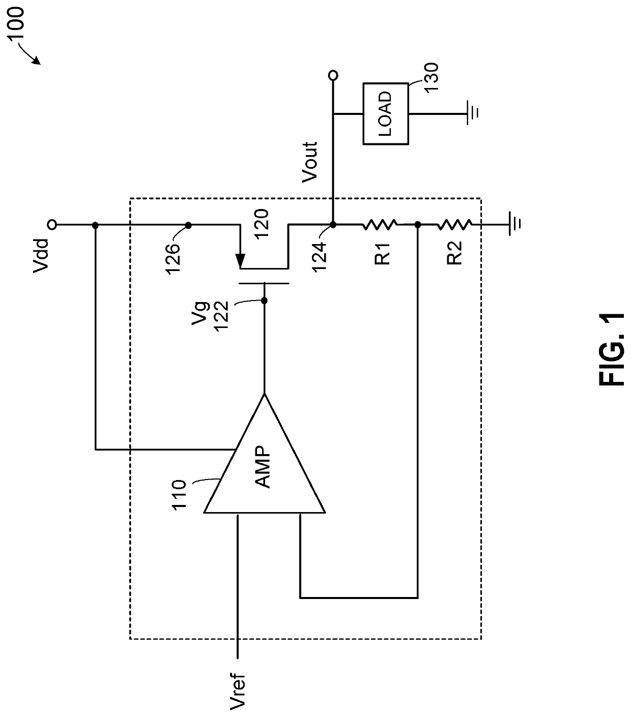
[0034]FIG. 1 is a simplified schematic diagram illustrating an example of a low-dropout voltage regulator (LDO) according to ...


PUM


Abstract

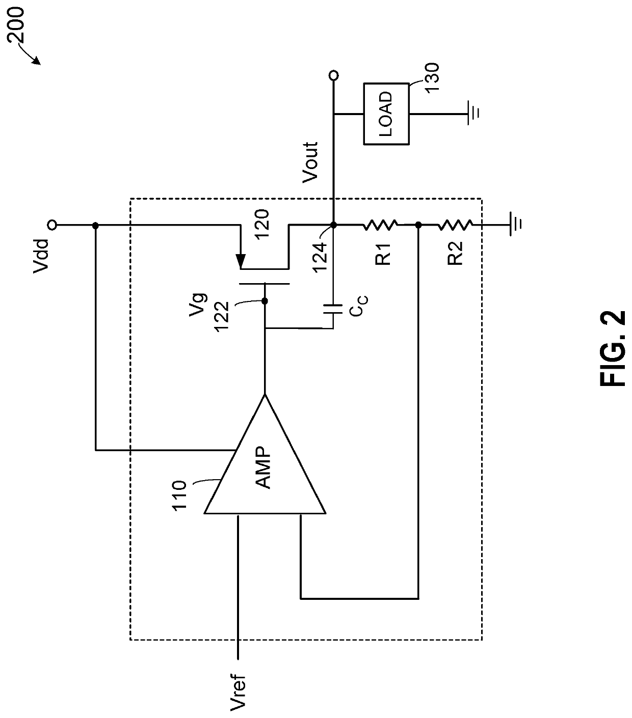
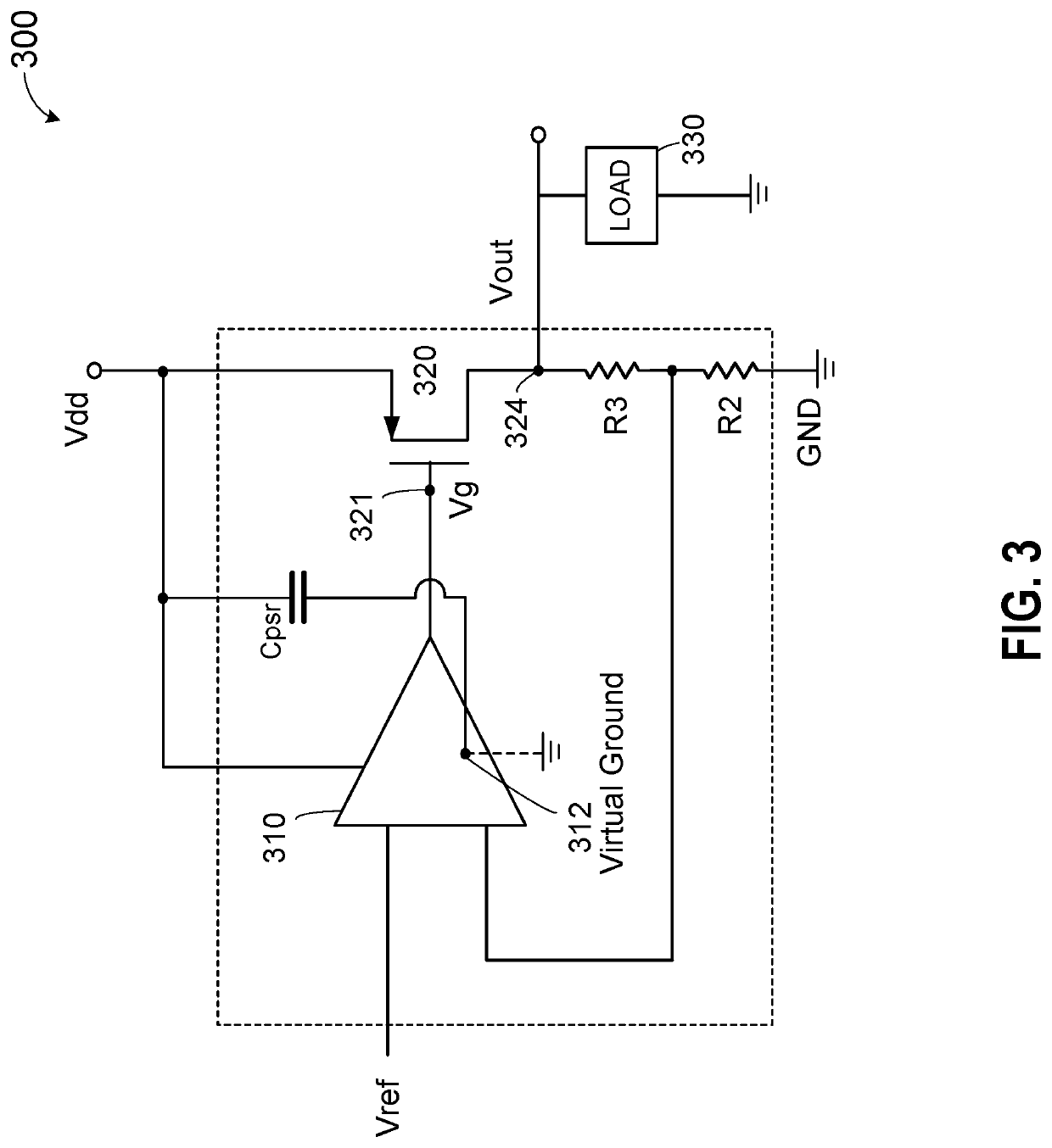
A voltage regulator circuit includes a power supply terminal and a ground terminal, and a differential amplifier coupled between the power supply terminal and the ground terminal. The voltage regulator circuit also includes an output transistor, which includes a gate node coupled to an output node of the differential amplifier to receive a gate voltage and to provide a regulated output voltage at an output node of the output transistor. The differential amplifier is configured to provide the gate voltage based on a differential between a reference voltage and the regulated output voltage. The voltage regulator also includes a compensation capacitance coupled between a virtual ground node in the differential amplifier and either the power supply terminal or the ground terminal and a virtual ground node in the differential amplifier.

Description

CROSS-REFERENCES TO RELATED APPLICATIONS[0001]This application is related to U.S. patent application Ser. No. 16 / 699,076, entitled “DISTRIBUTED LOW-DROPOUT VOLTAGE REGULATOR (LDO) WITH UNIFORM POWER DELIVERY,” filed concurrently, the content of which is incorporated by reference herein.BACKGROUND OF THE INVENTION[0002]Voltage regulators, in particular linear voltage regulators, are devices that are used to maintain a steady voltage. A low-dropout or LDO regulator is a DC linear voltage regulator that can regulate the output voltage even when the supply voltage is very close to the output voltage. Such voltage regulators have broad applicability. For example, voltage regulators may be utilized with analog-to-digital converters (ADC), application specific integrated circuits (ASICs), field programmable gate arrays (FPGAs) and other high performance / high power products. The voltage regulators may provide clean (e.g., steady) output voltage to one or more components of these high perfor...

Claims


Application Information

Patent Timeline
Patent Type & Authority Patents(United States)
IPC IPC(8): G05F1/575
CPCG05F1/575
Inventor WEI, DAZHI
Owner SHENZHEN GOODIX TECH CO LTD
Learn More