
Method and system for operating a gaseous fuel vehicle

a gaseous fuel and vehicle technology, applied in the direction of machines/engines, battery/fuel cell control arrangements, battery/cell propulsion, etc., can solve the problems of limited gaseous fuel that may be stored onboard the vehicle, reduced etc., to improve engine starting, reduce engine emissions, and reduce the range of gaseous fuel vehicles

Active Publication Date: 2021-06-22
FORD GLOBAL TECH LLC
View PDF19 Cites 0 Cited by
  • Summary
  • Abstract
  • Description
  • Claims
  • Application Information

AI Technical Summary

Benefits of technology

[0002]A vehicle may include an internal combustion engine to provide propulsive torque to the vehicle and to charge an electric energy storage device (e.g., a battery or a capacitor). The engine may combust a fuel (e.g., hydrogen, liquefied petroleum gas, or compressed natural gas and referred to herein as a gaseous fuel) that is in a gaseous state at a defined ambient temperature (e.g., 70° F.) and pressure (e.g., 14.7 pounds per square inch). The gaseous fuel may reduce engine emissions and improve engine starting during cold engine operating conditions, but the amount of gaseous fuel that may be stored onboard the vehicle may be limited based on environmental conditions. For example, a gaseous fuel tank may be rated to hold an amount of fuel equal to 20 gallons gasoline equivalent (GGE) of compressed natural gas at 70° Fahrenheit, which corresponds to a pressure of 3600 pounds per square inch (PSI). However, the same gaseous fuel tank may be filled with only 15 GGE of compressed natural gas at temperature that is higher than 70° F. because of the gaseous fuel tank's pressure limits and because filling stations may include filling devices that limit the amount of gaseous fuel that may be provided to a vehicle's fuel tank based on pressure in the fuel tank and ambient temperature. Thus, range of a gaseous fuel vehicle may be reduced because of fuel tank pressure constraints and ambient environmental conditions. As such, it may be desirable to provide a way of reducing variation of a gaseous fuel tank filling amount in view of varying environmental conditions so that a vehicle's driving range after filling the fuel tank to its capacity may be more consistent.
[0004]By cooling the gaseous fuel storage tank in response to filling the gaseous fuel storage tank with fuel, it may be possible to provide more consistent GGE fuel amounts stored in gaseous fuel storage tank over a wider range of ambient environmental temperatures. For example, during filling of a gaseous fuel storage tank, compression work performed on gaseous fuel may increase a temperature of the gaseous fuel stored in the gaseous fuel storage tank and it may increase a temperature of the gaseous fuel storage tank. The temperature increases may act to reduce the amount of fuel that may be stored in the gaseous fuel storage tank because of gaseous fuel storage tank pressure limits. However, by cooling the gaseous fuel storage tank during filling of the gaseous fuel storage tank, it may be possible to reduce pressure within the gaseous fuel storage tank so that the GGE amount of fuel stored in the fuel tank may be increased without exceeding gaseous fuel tank pressure limits.
[0005]The present description may provide several advantages. For example, the approach may allow more consistent GGE amounts of fuel to be stored within a gaseous fuel storage tank. Further, the approach may allow a temperature of a battery to be increased via heat transferred from the gaseous fuel storage tank to the battery, thereby reducing consumption of energy from the battery. In addition, the approach may be implemented in a variety of ways including but not limited to via a heat pump or via a glycol cooling circuit.

Problems solved by technology

The gaseous fuel may reduce engine emissions and improve engine starting during cold engine operating conditions, but the amount of gaseous fuel that may be stored onboard the vehicle may be limited based on environmental conditions.
However, the same gaseous fuel tank may be filled with only 15 GGE of compressed natural gas at temperature that is higher than 70° F. because of the gaseous fuel tank's pressure limits and because filling stations may include filling devices that limit the amount of gaseous fuel that may be provided to a vehicle's fuel tank based on pressure in the fuel tank and ambient temperature.
Thus, range of a gaseous fuel vehicle may be reduced because of fuel tank pressure constraints and ambient environmental conditions.

Method used


Image

  • Method and system for operating a gaseous fuel vehicle
  • Method and system for operating a gaseous fuel vehicle
  • Method and system for operating a gaseous fuel vehicle

Examples


Embodiment Construction

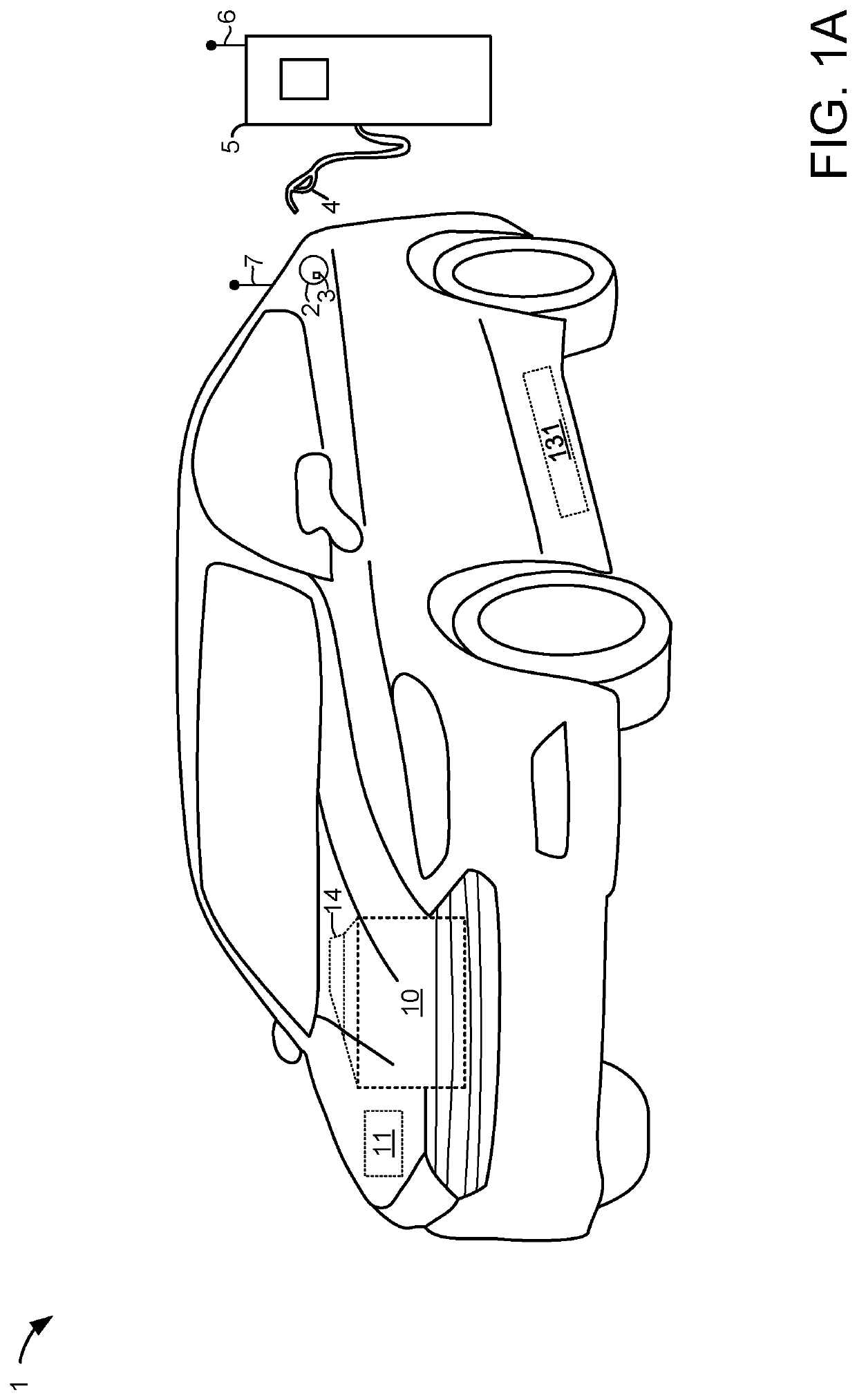
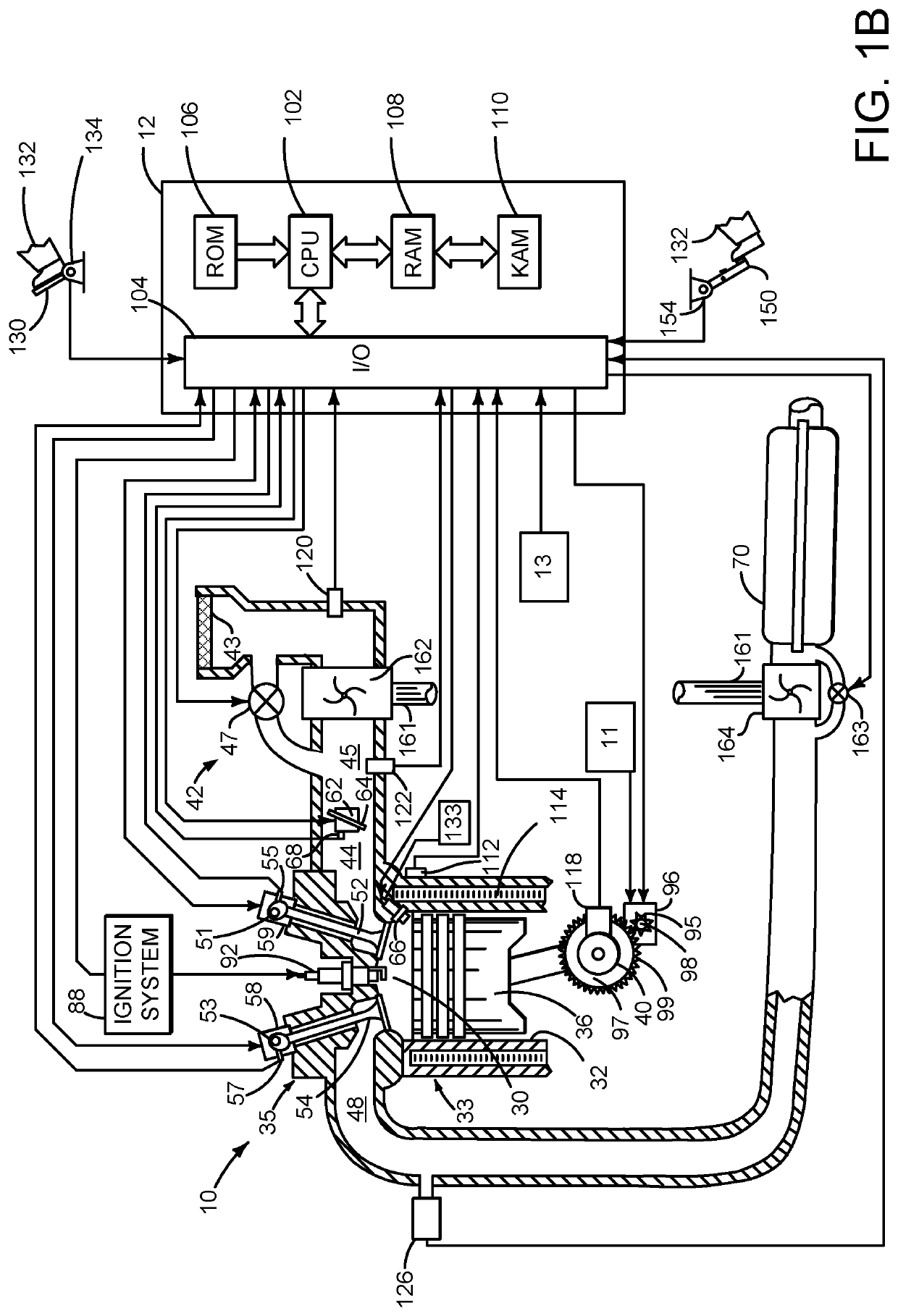
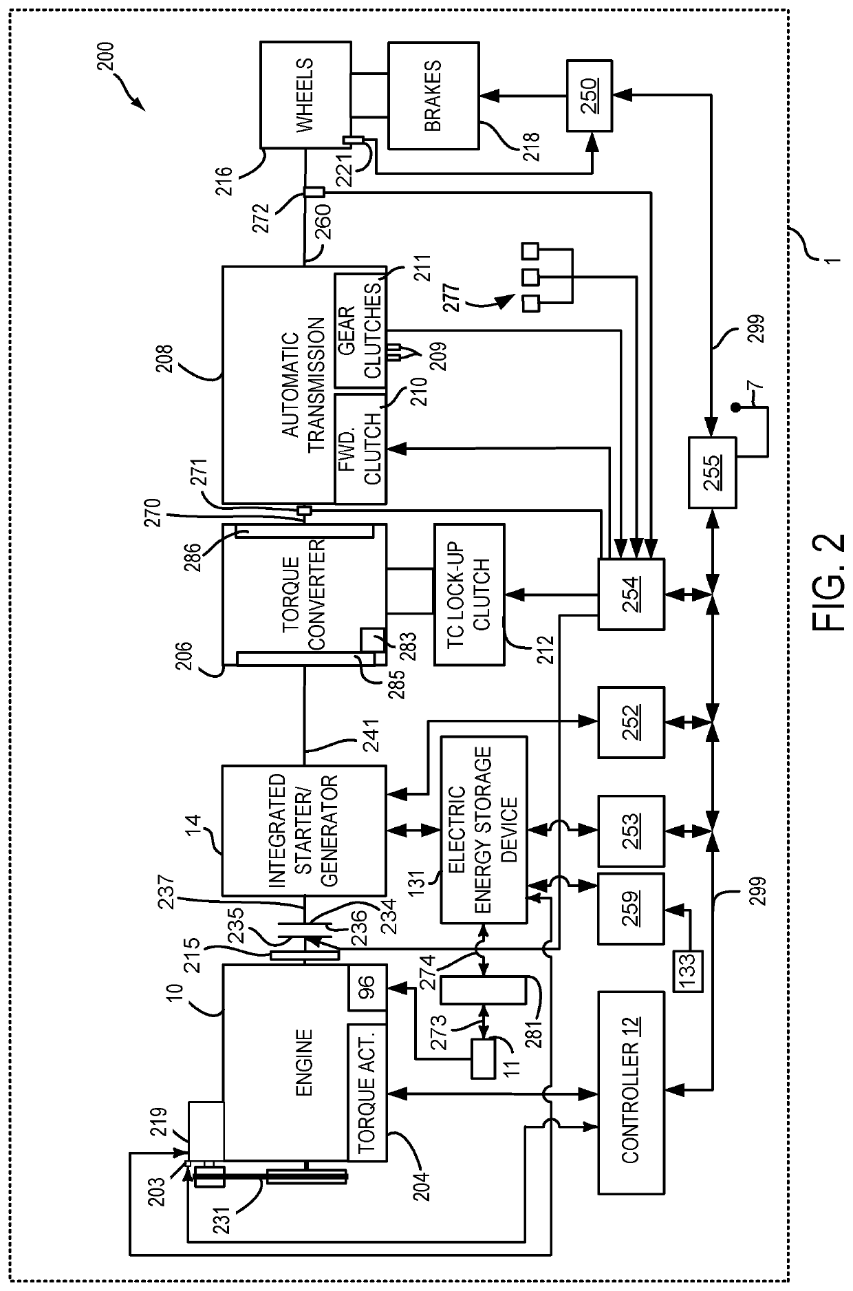
[0016]The present description is related to operating a vehicle that includes a gaseous fuel storage tank. The vehicle may include an internal combustion engine and an electric machine for propelling the vehicle as is shown in FIGS. 1A-2. The vehicle may include one or more cooling circuits for cooling the gaseous fuel tank as shown in FIGS. 3A and 3B. The vehicle may be operated according to the sequence of FIG. 4 and according to the method of FIG. 5.

[0017]Referring to FIG. 1A, a vehicle 1 including an engine 10, an electric machine 14, a first electrical energy storage device 11, and a second electrical energy storage device 131 is shown. In one example, the vehicle 1 may be propelled solely via the engine 10, solely via the electrical machine 14, or by both the engine 10 and the electrical machine 14. The electrical machine 14 may be supplied electrical power via the second electrical energy storage device 131. Thus, second electric energy storage device 131 may be referred to a...


PUM


Abstract

Methods and systems for operating a vehicle that includes an internal combustion engine and a gaseous fuel storage tank are presented. In one example, the gaseous fuel storage tank is cooled so that an amount of gaseous fuel that may be stored in the gaseous fuel tank may be increased to extend a vehicle's driving range.

Description

FIELD[0001]The present description relates to methods and a system for storing and consuming gaseous fuel in a wheeled vehicle. The methods and system may be particularly useful for vehicles that include hybrid powertrains.BACKGROUND AND SUMMARY[0002]A vehicle may include an internal combustion engine to provide propulsive torque to the vehicle and to charge an electric energy storage device (e.g., a battery or a capacitor). The engine may combust a fuel (e.g., hydrogen, liquefied petroleum gas, or compressed natural gas and referred to herein as a gaseous fuel) that is in a gaseous state at a defined ambient temperature (e.g., 70° F.) and pressure (e.g., 14.7 pounds per square inch). The gaseous fuel may reduce engine emissions and improve engine starting during cold engine operating conditions, but the amount of gaseous fuel that may be stored onboard the vehicle may be limited based on environmental conditions. For example, a gaseous fuel tank may be rated to hold an amount of fu...

Claims


Application Information

Patent Timeline
Patent Type & Authority Patents(United States)
IPC IPC(8): B60L58/27F01P3/20F02M21/02F01P3/18F01P5/12F01P3/22B60K6/24F01P7/14
CPCF01P3/20B60K6/24B60L58/27F01P3/18F01P3/22F01P5/12F01P7/14F02M21/0221B60Y2200/92Y10S903/903B60K15/03B60K15/03006B60K2015/03019B60K2015/03414B60L1/003B60L1/02B60L2240/36B60L50/61F01P2050/24F01P2060/08F01P2060/10Y02T10/30Y02T10/62Y02T10/70
Inventor JIANG, ZHENMEROUX, DOMINIQUE
Owner FORD GLOBAL TECH LLC
Learn More