
Abnormality diagnosis system for air flow meter

a technology of abnormality diagnosis and air flow meter, which is applied in the direction of machines/engines, electric control, combustion engines, etc., can solve the problem and achieve the effect of small abnormality diagnosis chance and stable detection signal

Active Publication Date: 2021-07-06
TOYOTA JIDOSHA KK
View PDF29 Cites 3 Cited by
  • Summary
  • Abstract
  • Description
  • Claims
  • Application Information

AI Technical Summary

Benefits of technology

The patent text describes a system for diagnosing abnormalities in an air flow meter used in an engine. The system uses data on the load detected by the air flow meter and an estimated value of the load to diagnose any abnormalities. The system also takes into account the condition of the engine when the load is calculated. By analyzing changes in the engine load, the system can better diagnose abnormalities and confirm the normality of the air flow meter under multiple conditions. Overall, the system can make more accurate and reliable diagnoses.

Problems solved by technology

Thus, chances of abnormality diagnosis are small.

Method used


Image

  • Abnormality diagnosis system for air flow meter
  • Abnormality diagnosis system for air flow meter
  • Abnormality diagnosis system for air flow meter

Examples


Embodiment Construction

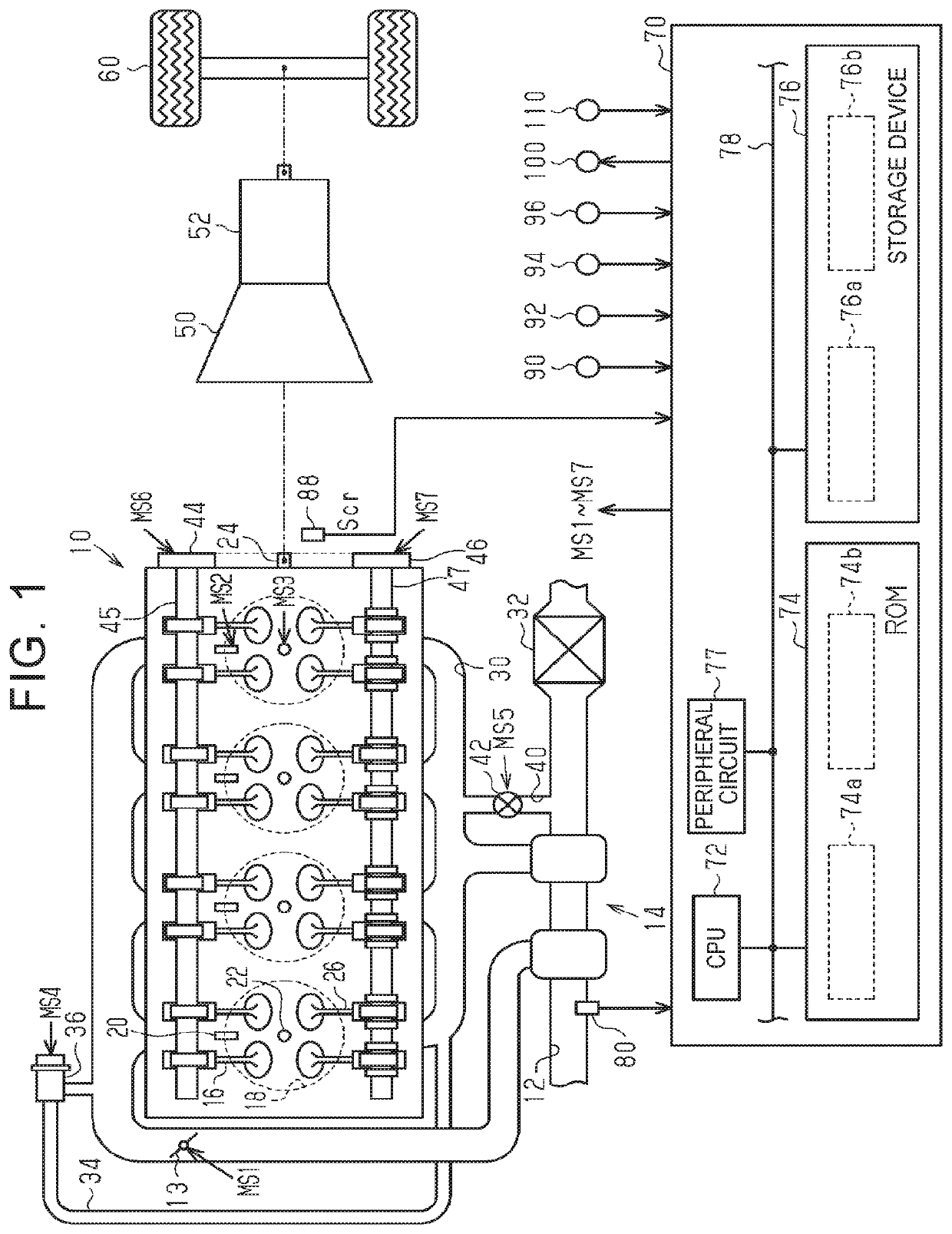
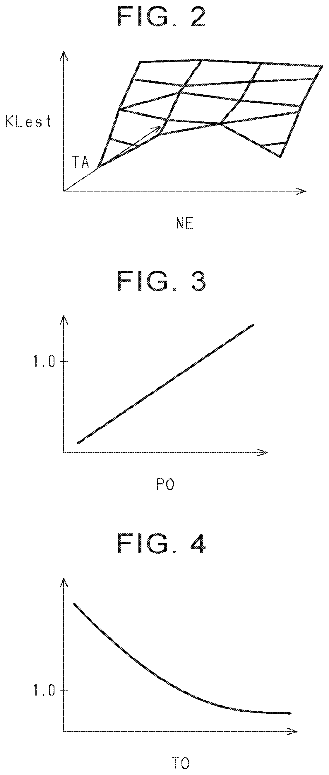
[0028]An abnormality diagnosis system for detecting an abnormality in an air flow meter according to one embodiment will be described with reference to FIG. 1 to FIG. 7. In an engine 10 installed on a vehicle shown in FIG. 1, a throttle valve 13 is provided in an intake passage 12. Air introduced through the intake passage 12 flows downstream via a supercharger 14, and flows into combustion chambers 18 when intake valves 16 are opened. In the engine 10, fuel injection valves 20 that directly inject fuel into the combustion chambers 18, and ignition devices 22 that generate spark discharge are provided. In the combustion chambers 18, a mixture of air and fuel is subjected to combustion, and energy generated through combustion is taken out as rotational energy of a crankshaft 24 as an output shaft of the engine 10. The mixture subjected to combustion is discharged, as exhaust gas, into an exhaust passage 30 when exhaust valves 26 are opened. A three-way catalyst 32 having oxygen stora...


PUM


Abstract

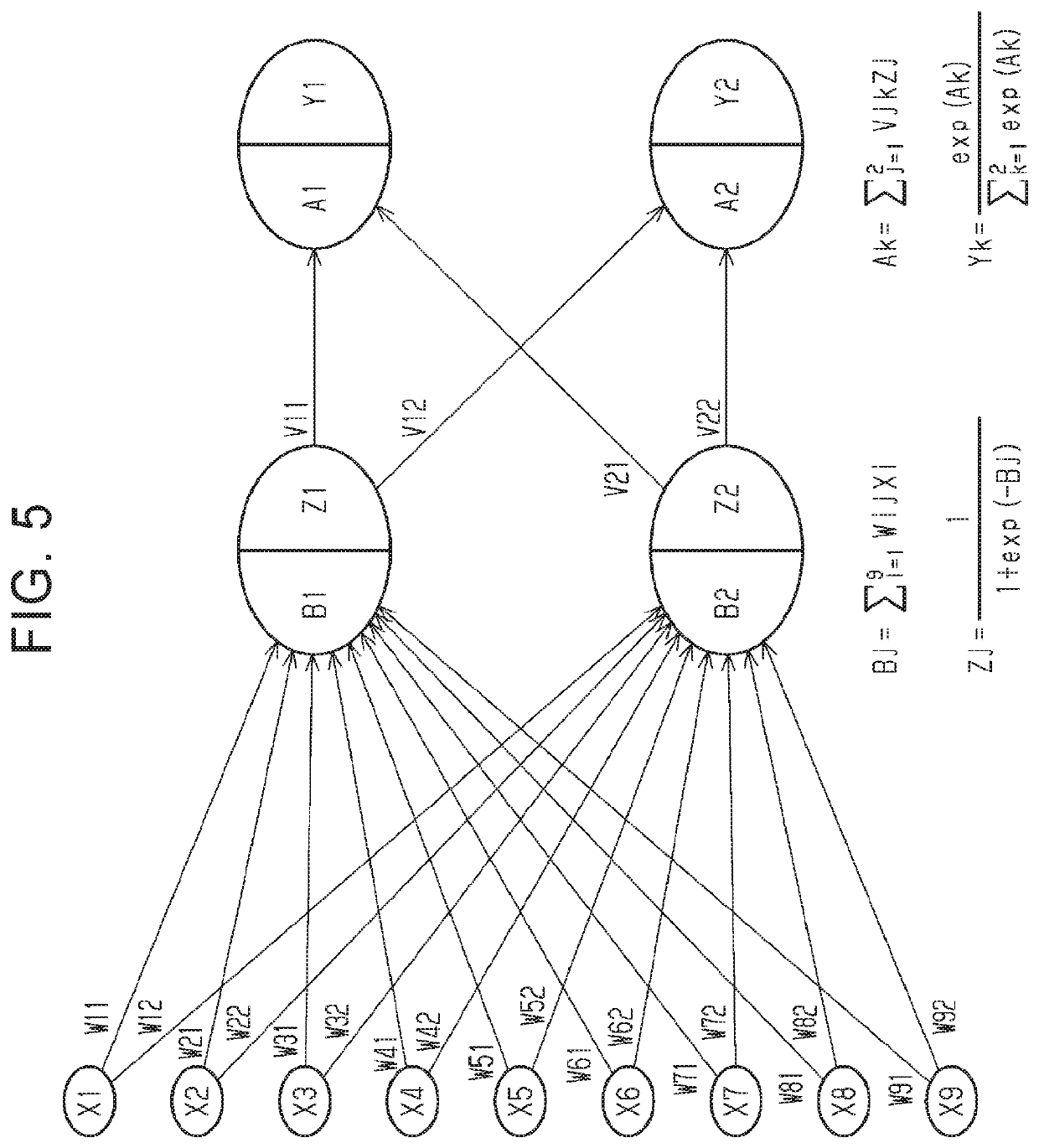
A storage device of a control system stores a trained neural network that is trained by using training data to which information as to whether there is an abnormality in an air flow meter is given as a true label. The trained neural network receives, as inputs, condition index values including the opening of a throttle valve and the engine speed, a load detected value calculated based on a detection signal of the air flow meter, a load estimated value estimated without using the detection signal of the air flow meter, and a change index value indicating the degree of change of the engine load. A CPU of the control system executes a diagnostic process to determine whether there is an abnormality in the air flow meter, using the neural network, which receives the condition index values, load detected value, load estimated value, and change index value as the inputs.

Description

INCORPORATION BY REFERENCE[0001]The disclosure of Japanese Patent Application No. 2020-000803 filed on Jan. 7, 2020 including the specification, drawings and abstract is incorporated herein by reference in its entirety.BACKGROUND1. Technical Field[0002]The present disclosure relates to an abnormality diagnosis system for an air flow meter.2. Description of Related Art[0003]An abnormality diagnosis system for an air flow meter is disclosed in Japanese Unexamined Patent Application Publication No. 2010-48133 (JP 2010-48133 A). When the operating state of a vehicle-mounted engine satisfies a particular abnormality detection condition, and a relatively stable detection signal can be obtained from an air flow meter, the abnormality diagnosis system compares the intake air amount calculated based on the detection signal of the air flow meter, with an allowable range calculated according to the operating state of the engine. Then, the abnormality diagnosis system determines that there is a...

Claims


Application Information

Patent Timeline
Patent Type & Authority Patents(United States)
IPC IPC(8): F02D41/18F02D41/22F02D41/24F02D13/02F02D41/14
CPCF02D41/222F02D13/0215F02D41/1405F02D41/18F02D41/2441F02D2200/0404F02D2200/101F02D41/22F02D45/00F02D41/045F02D2041/001F02D13/0219Y02T10/12Y02T10/40
Inventor YAMADA, KAZUHIRO
Owner TOYOTA JIDOSHA KK
Learn More