Method for manufacturing a nucleotide detector

Inactive Publication Date: 2006-10-31
PANASONIC CORP
View PDF16 Cites 2 Cited by
  • Summary
  • Abstract
  • Description
  • Claims
  • Application Information

AI Technical Summary

Benefits of technology

[0032]An object of the present invention is to provide a nucleotide detector capable of detecting target nucleotide (DNA, RNA, or the like) with high precision.
[0033]Another object of the present invention is to provide a method for easily producing a two-dimensional crystal film made of particulates of protein or the like having a diameter of the order of nanometers arranged at high density and at desired positions with high precision.
[0035]Either one of a pair of nucleotide molecules capable of conjugating with each other is bonded to each of the metal particles placed regularly on the substrate. Therefore, the conjugation between the one nucleotide molecule and the other nucleotide molecule capable of conjugating with the former can be established in uniform over the substrate. Thus, when the other nucleotide molecule is made detectable with a fluorescent label or the like, for example, a stable detection signal can be obtained.
[0041]According to the method for producing a particulate film of the present invention, by gradually raising or lowering the level of the liquid, the liquid level slightly rises along the substrate at the interface between the liquid and the substrate, forming a meniscus portion. Since the meniscus portion has a large surface area, a dispersion medium of the liquid evaporates, resulting in reduction of the amount of the dispersion medium in the meniscus portion. This causes an effect similar to the micro-capillary effect in the meniscus portion, where the liquid flows toward this portion. As a result, the particles exist in the meniscus portion of the liquid in a significantly high concentration, and thus are arranged on the surface of the substrate at high density with high precision. In other words, a film of particulates arranged at high density with high precision is formed on the surface of the substrate.

Problems solved by technology

However, this method requires an exceedingly long time and therefore is not practical as a method for detecting genetic information on many subjects.
From this point, also, it is clear that the conventional determination method is not practical.
However, the form of a colloid solution is disadvantageous when the functions of the particulates are to be effectively used.
It is difficult to keep the lifting rate constant when the rate is low.
In addition, the array of ultra-fine particles of the film may possibly lose uniformity due to vibration and the like that may be generated during lifting of the substrate 11.
For these reasons, it is difficult to apply the above method to ultra-fine particles.
If the above requirement described in relation with the first prior art fails to be realized, the DNA chip causes various problems.
Specifically, it is difficult to determine whether the fluorescence intensity is low because the absolute amount of DNA placed is small or because the absolute amount DNA placed is so large that emission of fluorescence is allowed despite of weak non-specific adsorption.
This may results in mistake of the determination.
Furthermore, the variation in the absolute amount of DNAs placed among chips indicates that the reproducibility of the chip quality is poor.
This may results in generation of defective DNA chips.
By these changes, the reproducibility of the quality of the particulate films deteriorates.
However, it is not easy to actually provide these means.
Therefore, the method disclosed by Nagayama et al. finds difficulty in providing particulate films with a uniform quality, and thus is not suitable for applications to formation of a particulate film over a large-area substrate and to mass production of particulate films.
In addition, using a large-size blade 21 made of platinum costs high.
However, if the blade 21 is made of a material other than platinum, it may possibly be corroded.
Moreover, it is very difficult to produce a large-size rigid blade having nanometer-order surface precision.
However, all of these methods are not suitable for mass production.

Method used


Image

  • Method for manufacturing a nucleotide detector
  • Method for manufacturing a nucleotide detector
  • Method for manufacturing a nucleotide detector

Examples


example 1

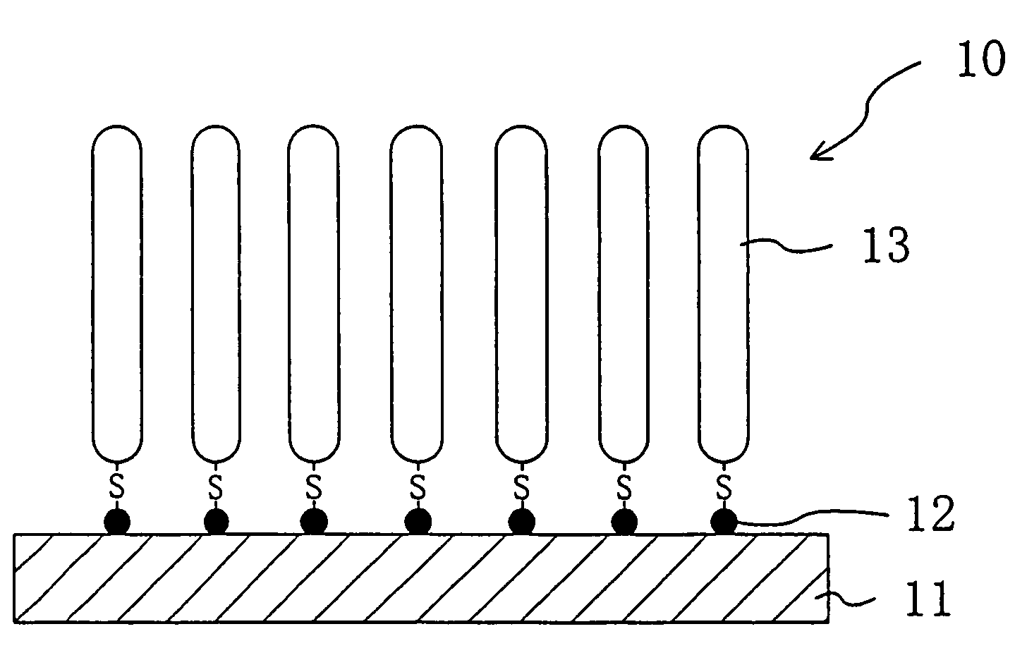
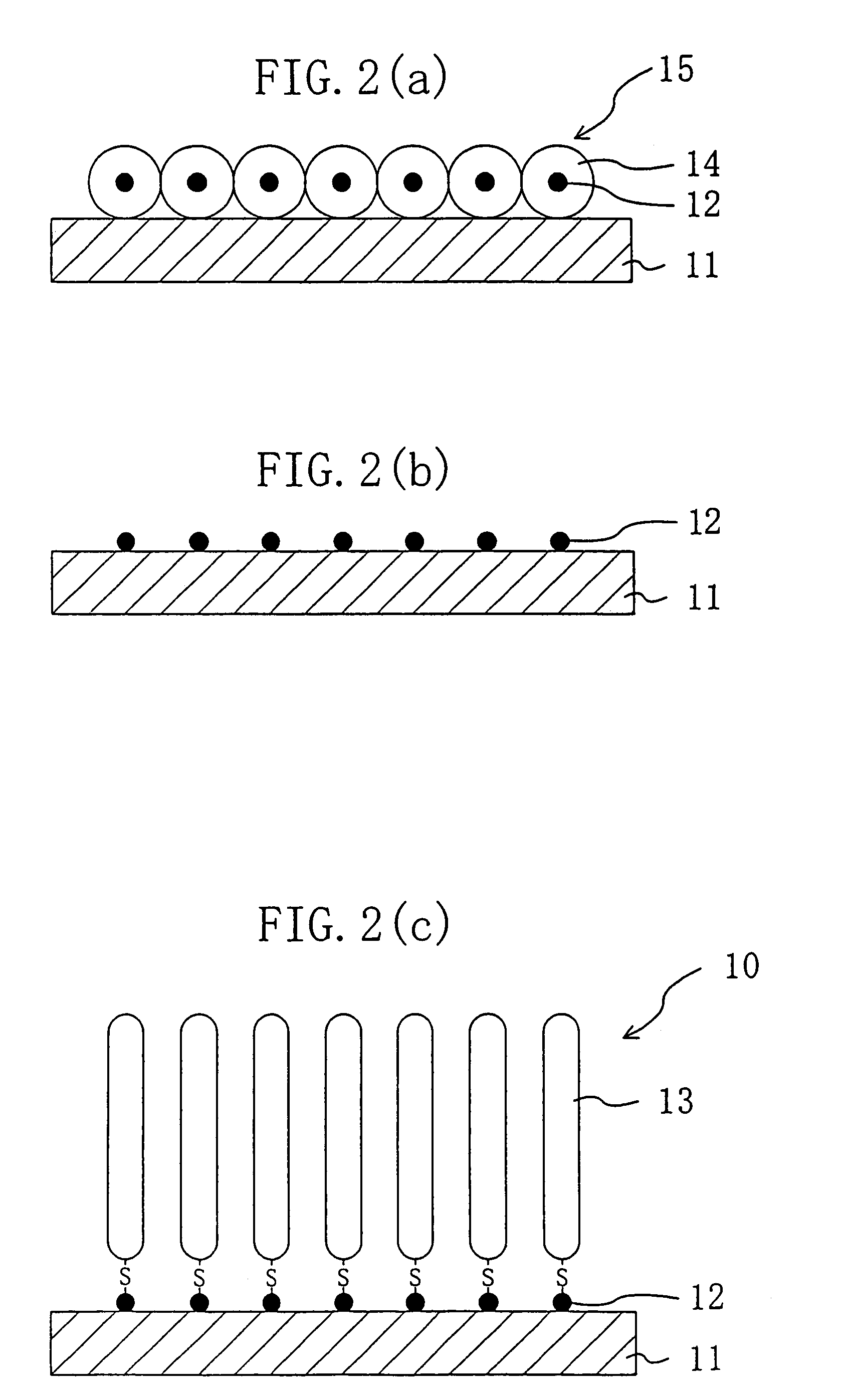
[0186]On a surface of a silicon substrate subjected to hydrophilic treatment with active ozone under ultraviolet irradiation at 110° C., apoferritin particles containing gold particles inside were arranged two-dimensionally at high density with high precision as shown in FIG. 2(a) by method 5 described above. For this process, used was a liquid containing gold particle-containing apoferritin in a normal saline solution in a concentration of 50 mg / ml. The liquid was drawn out from a container containing the liquid with a syringe at a drawing rate (liquid level lowering rate) of 0.1 mm / min.

[0187]The thus-produced substrate was heat-treated in a nitrogen gas atmosphere at 450° C. for one hour, to remove the apoferritin as the protein moiety and thus attain a substrate with only gold particles placed thereon in the shape of dots two-dimensionally at high density with high precision.

[0188]The resultant substrate was then put in contact with a thiol DNA aqueous solution, to attain a DNA s...

example 2

[0192]An RNA sensor was produced in the same manner as that described in Example 1, except that thiol RNAs (thiol RNAs produced using mRNAs obtained by transcription of T4 phages with sulfur atoms bonded to ends of the mRNAs) was used in place of the thiol DNA.

[0193]Using the resultant RNA sensor, a detection test was performed for separately synthesized complementary RNA. As a result, high fluorescence intensity was exhibited stably, and thus detection was very easy.

example 3

[0194]First, as in Example 1, gold particles were placed two-dimensionally on a silicon substrate. A resin resist film made of polymthyl methacrylate (PMMA) was then formed on the substrate, and a photomask having openings was formed on the resin resist film.

[0195]Subsequently, the substrate was irradiated with light from above of the photomask, and then treated with a developer to pattern the resin resist film, to thereby expose part of the gold particles on the substrate.

[0196]Thereafter, thiol DNAs were bonded to the gold particles on the substrate.

[0197]The above operation was repeated while the type of the thiol DNAs (in base sequence or the like) to be bonded to the exposed gold particles was changed one after another, to attain a multi-type DNA sensor with DNAs having a number of different sequences bonded to the substrate. As the thiol DNAs, T4 phage DNAs were used, and sulfur atoms were bonded to ends of the DNAs. A solution containing such thiol DNAs in a concentration of ...


PUM

PropertyMeasurementUnit
Temperatureaaaaaaaaaa
Sizeaaaaaaaaaa

Abstract

A nucleotide detector 10 includes: metal particles 12 having a size of the order of nanometers (diameter: about 6 nm) placed on a surface of a substrate 11 at high density with high precision (with spaces of about 12 nm between adjacent particles); and single-stranded DNAs (thiol DNAs) 13 having sulfur atoms at ends bonded to the gold particles 12. The thiol DNAs 13 are placed uniformly over the entire substrate 11 at high density with high precision. Therefore, once a fluorescence-labeled single-stranded DNA is hybridized with any of the thiol DNAs 13, high fluorescence intensity is stably obtained. This detector is therefore usable as a high-performance DNA sensor with a high SN ratio.

Description

TECHNICAL FIELD[0001]The present invention relates to a technology for using a film made of particulates placed with high precision, and more particularly, to a technology used suitably for manufacture of a nucleotide detector and the like.BACKGROUND ART[0002]First Prior Art[0003]Presently, thanks to the international human genome project and efforts of researchers involved in the project, it is definite that the genome DNA sequence of the human species will be completely clarified in coming several years. However, the genome DNA sequence (base sequence (gene arrangement)) concerned is a genome DMA sequence of a specific person, and not that of an individual. The genome DNA sequence of an individual is slightly different from that of the specific person, where substitution, deletion, insertion, and the like of a base may have occurred in a gene. Normally, such a slight difference is not critical and does not cause any trouble in the life of the individual.[0004]However, it has also ...

Claims


Application Information

Patent Timeline
IPC IPC(8): C12Q1/68C07H21/04C12M1/36G01N15/06C12M1/26C12M1/32C40B40/06
CPCC12Q1/6825C12Q1/6837B01J2219/00648B01J2219/00722C40B40/06C12Q2565/507
Inventor YAMASHITA, ICHIRO
Owner PANASONIC CORP
Why Eureka
Try Eureka