
Method and apparatus for mitigating performance degradation in digital low-dropout voltage regulators (DLDOs) caused by limit cycle oscillation (LCO) and other factors

Active Publication Date: 2021-08-24
UNIV OF SOUTH FLORIDA +1
View PDF8 Cites 3 Cited by
  • Summary
  • Abstract
  • Description
  • Claims
  • Application Information

AI Technical Summary

Benefits of technology

The patent text describes a circuit that can improve the performance of a specific component called a DLDO. The circuit includes a clocked comparator, a set of N power transistors, a digital controller, and a circuit that reduces the width of clock signals. These components work together to address issues that can degrade the performance of the DLDO. The result is a better performing DLDO that can handle higher frequencies and voltages with greater efficiency.

Problems solved by technology

For example, it has been observed that the emerging recognition, mining, and synthesis applications can tolerate errors in the data flow but not in control.
BTI can induce threshold voltage increase and consequent circuit-level performance degradation.
This scheme can therefore introduce serious degradation to M1 to Mm due to NBTI.
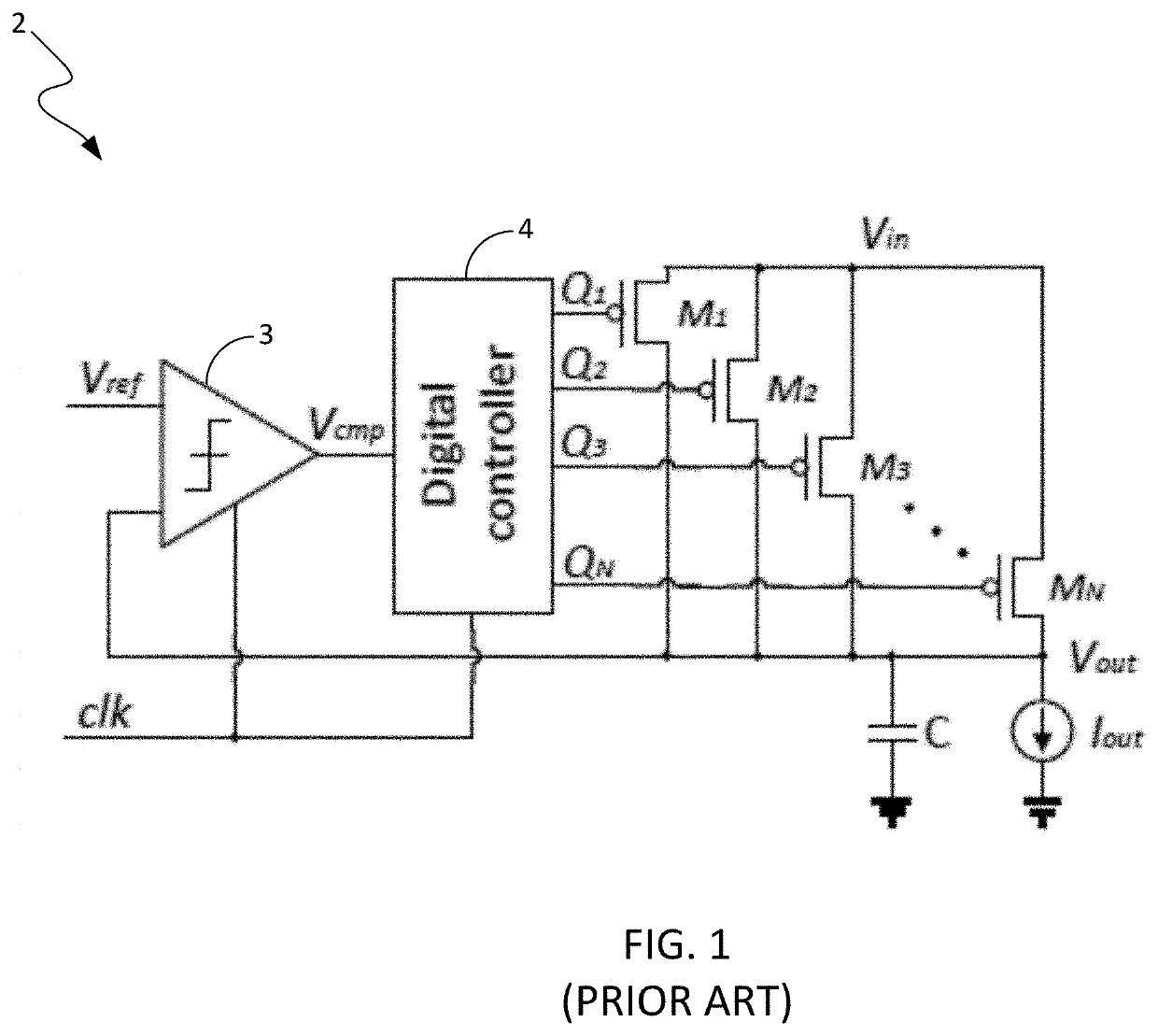
Furthermore, DLDOs experience inherent limit cycle oscillation (LCO) in steady state due to inherent quantization errors.
A larger LCO mode under a certain load current Load and clock frequency fclk conditions may lead to larger steady-state output voltage ripple, which can degrade the performance of the DLDO.
Larger delay between the clocked comparator and shift register is detrimental to LCO.
Control heavy components, on the other hand, should not be permitted to leave the error-free zone to avoid catastrophic program termination or excessive loss in program output quality even if the program does not crash.
Additionally, in certain processor components that can show higher degrees of tolerance to errors, the regulators can be intentionally under-designed to save valuable chip area and potentially power-conversion efficiency.
The quality of the supply voltage directly affects the data path delay and signal quality, and fluctuations in the supply voltage result in delay uncertainty and clock jitter.
To date, only a limited amount of work has been done on the reliability of on-chip voltage regulators.
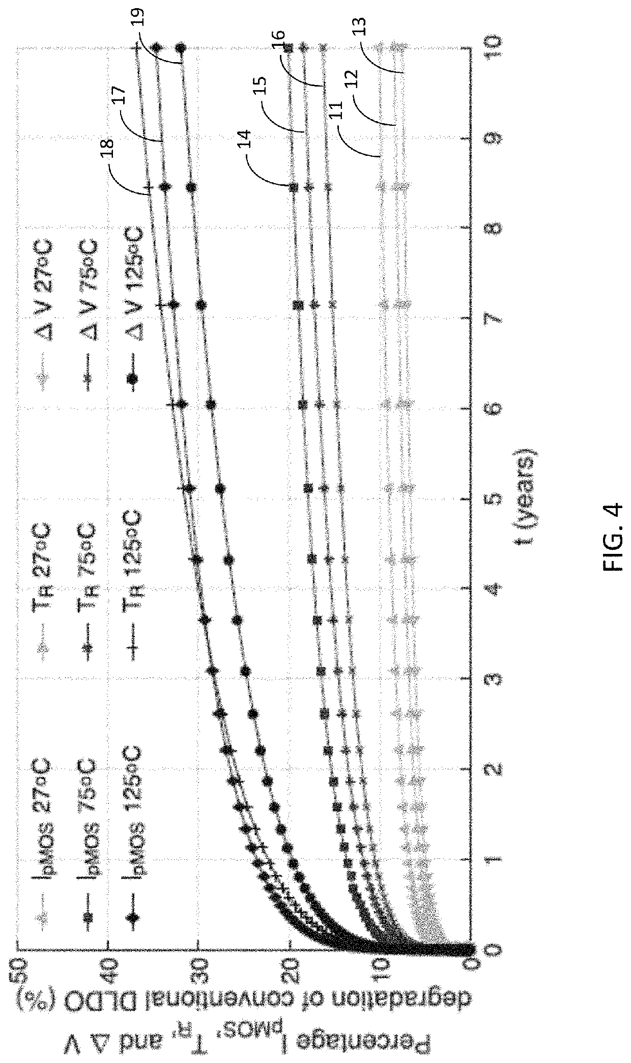
However, as pMOS is used as the power transistor for DLDOs, NBTI-induced degradations largely affect important performance metrics such as the maximum output current capability Imax, load response time TR, and magnitude of the droop ΔV.
Meanwhile, as indicated above, the combined NBTI- and PBTI-induced control loop degradations can potentially increase the mode of LCOs within DLDOs and adversely affect the steady-state output voltage ripple performance.
NBTI can introduce significant Vth degradations to pMOS transistors due to negatively applied gate to source voltage Vgs.
Degraded IpMOS can further lead to reduced Imax and lower output voltage regulation capability under high load current.
The delay between the operation of the shift register and fluctuation of the output voltage, together with the quantization effects of the comparator and the delay between the sampling instant and the time of pMOS array actuation lead to the occurrence of LCO.
Transistor aging can lead to increased path delay.
This demonstrates the potential negative effect of the propagation delay of the shift register on LCO.
It should be noted that aging-induced propagation delay degradation is not a sufficient condition to incite a larger LCO mode.
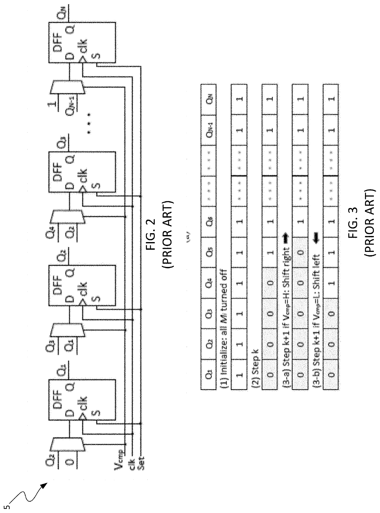
Reliability is not considered in conventional bDSR-based DLDO designs, and therefore too much stress is exerted on a small portion of Mis.
As little extra transistors are added per control stage and the bDSR only consumes a few μW power, the uDSR induced power overhead is also negligible.
However, a tradeoff exists between the steady-state quiescent current saving and reliability enhancement enabled by the unidirectional shift scheme.

Method used


Image

  • Method and apparatus for mitigating performance degradation in digital low-dropout voltage regulators (DLDOs) caused by limit cycle oscillation (LCO) and other factors
  • Method and apparatus for mitigating performance degradation in digital low-dropout voltage regulators (DLDOs) caused by limit cycle oscillation (LCO) and other factors
  • Method and apparatus for mitigating performance degradation in digital low-dropout voltage regulators (DLDOs) caused by limit cycle oscillation (LCO) and other factors

Examples


Embodiment Construction

"d_n">[0042]The present disclosure discloses a DLDO having a configuration that mitigates performance degradation of the DLDO caused by LCO. The DLDO comprises a clocked comparator, an array of power transistors, a digital controller and a clock pulsewidth reduction circuit. The clocked comparator and the digital controller have clock terminals for receiving a DLDO clock signal having a preselected pulsewidth. The digital controller comprises control logic configured to control signals that cause the power transistors to be turned ON or OFF in accordance with the preselected activation / deactivation control scheme. The clock pulsewidth reduction circuit comprises clock reduction logic configured to receive a clock signal having a first pulsewidth and to generate the DLDO clock signal having the preselected pulsewidth that is narrower that the first pulsewidth. The DLDO clock signal is delivered to the clock terminals of the clocked comparator and of the digital controller. The narrow...


PUM


Abstract

A DLDO has a configuration that mitigates performance degradation associated with limit cycle oscillation (LCO). The DLDO comprises a clocked comparator, an array of power transistors, a digital controller and a clock pulsewidth reduction circuit. The digital controller comprises control logic configured to generate control signals that cause the power transistors to be turned ON or OFF in accordance with a preselected activation / deactivation control scheme. The clock pulsewidth reduction circuit receives an input clock signal having a first pulsewidth and generates the DLDO clock signal having the preselected pulsewidth that is narrower that the first pulsewidth, which is then delivered to the clock terminals of the clocked comparator and the digital controller. The narrower pulsewidth of the DLDO clock reduces the LCO mode to mitigate performance degradation caused by LCO.

Description

CROSS-REFERENCE TO RELATED APPLICATIONS[0001]This application claims priority to, and the benefit of the filing date of, U.S. provisional application No. 62 / 729,728, filed on Sep. 11, 2018, entitled “Reduced Clock Pulse Width Digital Low-Dropout Regulator,” which is hereby incorporated by reference herein in its entirety.GOVERNMENT RIGHTS STATEMENT[0002]This invention was made with government support under grant No. CCF1350451 awarded by the National Science Foundation. The government has certain rights in this invention.TECHNICAL FIELD[0003]The invention relates to digital low-dropout voltage regulators (DLDOs).BACKGROUND[0004]Distributed on-chip voltage regulation in fine temporal and spatial granularity enables fast and timely control of the operating point. Thereby, the operating voltage and frequency can better match the needs of the workload to maximize energy efficiency. As a function of the workload, throughout the execution time, different components of a processor chip exh...

Claims


Application Information

Patent Timeline
IPC IPC(8): G05F1/59G05F1/614G05F1/563G05F1/56G05F1/575G05F1/565
CPCG05F1/59G05F1/56G05F1/563G05F1/565G05F1/575G05F1/614
Inventor KÖSE, SELÇUKWANG, LONGFEIKHATAMIFARD, S. KARENKARPUZCU, ULYA R.
Owner UNIV OF SOUTH FLORIDA
Learn More