Stone sense with fiber erosion protection and camera saturation prevention, and/or absence-detection safety interlock

a technology of fiber erosion protection and camera saturation prevention, applied in the field of laser surgery, can solve the problems of prolonging the operation time, compromising the safety of patients, and affecting the safety of patients, and achieve the effect of reducing erosion

Active Publication Date: 2021-09-07
OPTICAL INTEGRITY INC
View PDF8 Cites 2 Cited by
  • Summary
  • Abstract
  • Description
  • Claims
  • Application Information

AI Technical Summary

Benefits of technology

[0009]The present invention provides a way to determine the relative position of a fiber tip and a laser target. The invention can therefore be used to reduce erosion and endoscope camera saturation by providing early detection, before the occurrence of significant erosion or a camera-saturating-flash, of contact between the tip of the optical fiber and a stone. The invention can alternatively or additionally be used to detect that the target has moved away from, or is not present in, the path of the laser, and therefore avoid firing of the laser into a tissue other than the target.
[0010]The relative fiber tip-to-target detection is accomplished by using a spectrophotometer to detect radiation emissions (or reflections) indicative of the presence of a target at a predetermined position relative to the fiber tip. For example, the spectrophotometer may be used to detect emissions or reflections at a wavelength or wavelengths λ3 that occur upon contact between the fiber tip and a stone. Upon detection of contact, an alarm or other indication may be provided so that the fiber can be immediately pulled back away from the tissue, before erosion or a flash occurs. In addition, the delivery of radiation by the fiber can be temporarily stopped or reduced to give the surgeon time to react to the detection and pull back the fiber.

Problems solved by technology

Optical fibers can erode very quickly when making contact with kidney stones while performing laser lithotripsy.
This can prolong operative time and jeopardize the safety of the patient.
In addition, contact between the optical fiber and the stone can cause a flash that saturates the image from the endoscope camera, temporarily preventing the surgeon from viewing the treatment site, which can also jeopardize patient safety and prolong operative time.
However, a problem still exists in that the stone might not always be in the path of the laser during the lithotripsy procedure, which can cause retro repulsion of the stone, excess wear on the fiber and laser, and the potential for damage to equipment or tissues other than the stone that are in the direct path of the laser.

Method used


Image

  • Stone sense with fiber erosion protection and camera saturation prevention, and/or absence-detection safety interlock
  • Stone sense with fiber erosion protection and camera saturation prevention, and/or absence-detection safety interlock
  • Stone sense with fiber erosion protection and camera saturation prevention, and/or absence-detection safety interlock

Examples


Embodiment Construction

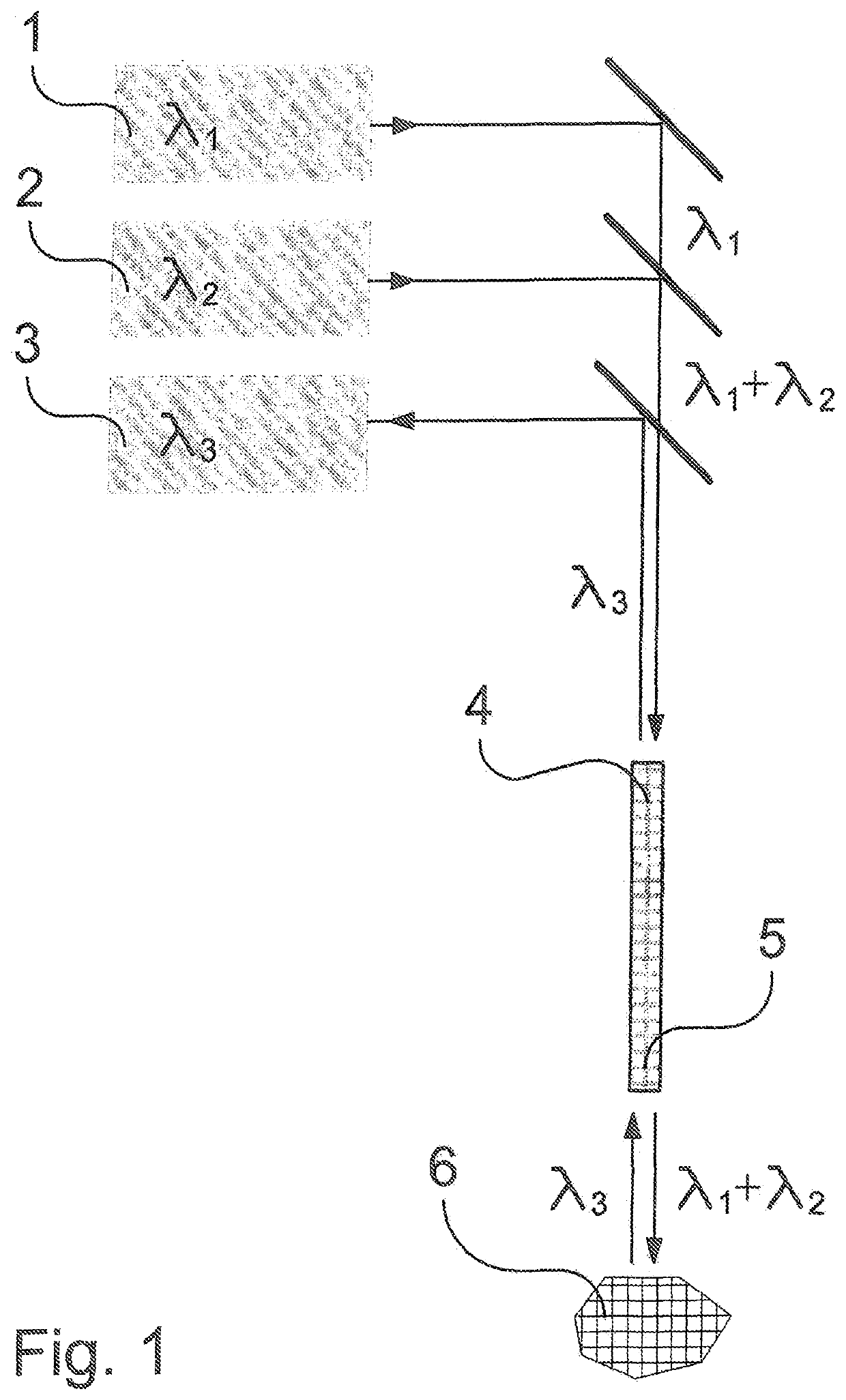
[0016]As illustrated in FIG. 1, the system of the invention includes a conventional laser delivery apparatus that includes a laser 1 capable of delivering stone vaporizing or destroying pulses during a laser lithotripsy procedure. The system may also include a secondary light source, which could be a laser or LED light source 2 that serves to provide an aiming beam, but which could also be an endoscope light, etc.

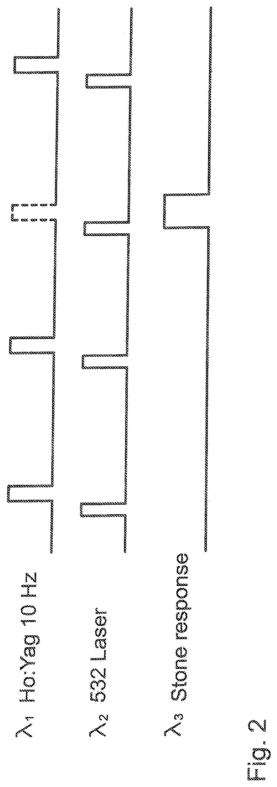
[0017]The main laser 1 may, by way of example and not limitation, be a Ho:YAG laser that outputs pulses of wavelength λ1 at a frequency of 10 Hz. In the illustrative example where a secondary light source 2, which may for example be any pulsed UV-VIS-IR laser, is included to provide an aiming beam. By way of example and not limitation, the aiming beam may have a wavelength λ2 of 532 nm (green) that causes the stone to fluoresce at the point of incidence, and that also has a pulse frequency of 10 Hz. The outputs of the of main laser 1 and secondary light source 2 are injecte...


PUM


Abstract

A system and method for detecting relative location of a surgical laser fiber tip relative to a surgical laser target during a surgical laser procedure utilizes a spectrophotometer to detect radiation indicative of the relative location. For example, the detected radiation may indicate contact between the fiber tip and a stone being subjected to laser lithotripsy, so as to prompt the surgeon to withdraw the fiber tip from the stone and / or take other action to limit contact-induced erosion of the fiber tip, and to avoid saturation of the endoscope camera resulting from the flash that occurs following contact. In addition, the absence of any detected radiation by the spectrophotometer may be used to indicate that the stone is no longer present, or that the fiber tip is no longer aimed at the stone, prompting the operator to reposition the fiber and / or temporarily cease firing of the laser. The main surgical laser may be a pulsed Holmium laser, which is delivered to the target through the optical fiber together with a pulsed 532 nm aiming beam.

Description

[0001]This application claims the benefit of provisional U.S. Patent Appl. Ser. Nos. 62 / 580,509, filed Nov. 2, 2017, and 62 / 513,791, filed Jun. 1, 2017, both of which are incorporated herein by reference.BACKGROUND OF THE INVENTION1. Field of the Invention[0002]The invention relates to the field of laser surgery, and in particular to detection of the relative position of a surgical laser fiber tip and target, such as a stone or other pathological entity or tissue, at which the laser is directed.[0003]The detection of relative position may be used to modulate the laser so that the laser pulses only occur at the most opportune moments, thereby expediting the procedure while also protecting surgical equipment and non-target tissue from extraneous pulses. By minimizing the laser pulses for each procedure, the laser and other equipment, including fibers and endoscopes, will experience less wear and increased longevity. Also, shorter surgical times will increase patient safety by reducing...

Claims


Application Information

Patent Timeline
Patent Type & Authority Patents(United States)
IPC IPC(8): A61B18/22A61B18/20
CPCA61B18/22A61B2018/2075A61B2018/2272A61B2018/22853A61B18/26A61B2018/263A61B2018/00505
Inventor BROWN, JOE D.MALPHURS, DANIEL
Owner OPTICAL INTEGRITY INC
Why Eureka
Try Eureka