Thermal management system for an electric drive system, preferably for a vehicle

a technology of electric drive system and management system, which is applied in the direction of electrical apparatus, electrical sub-unit features, electrical apparatus contruction details, etc., can solve the problems that the cooling of the power modules or other components of the actuator system cannot be altered or varied, and achieve the effect of reducing the total system loss and reducing the pumping power of the coolant pump

Active Publication Date: 2021-11-30
SCHAEFFLER TECH AG & CO KG
View PDF58 Cites 2 Cited by
  • Summary
  • Abstract
  • Description
  • Claims
  • Application Information

AI Technical Summary

Benefits of technology

[0005]According to the disclosure, the electric motor and the power electronics each are in spatial contact with a cooling unit, wherein the cooling units of the electric motor and the power electronics are disposed in parallel with each other and an electrically controlled coolant distributor comprising two outputs is positioned between the coolant pump and the cooling units, wherein in each case an output leads to the cooling unit for the electric motor or to the cooling unit for the power electronics, and the outputs of the cooling units are merged in a channel and fed back to the coolant pump. This has the advantage that owing to the delivery of coolant being divided into parallel branches, continuous power to the electrical drive system is increased by the selective cooling of the power electronics and the electric motor. Improved overall efficiency of the electrical drive system at partial load points is achieved by thermal operating point adjustment of the power electronics and electric motor components. Moreover, enhanced short-term performance of the electrical drive system is possible by thermal preconditioning of the power electronics and electric motor components to provide a larger temperature difference. The service life of the components is increased by the demand-led cooling of the power electronics and the electric motor. Said thermal management system also provides advantages with the integration of the electrical drive system that is equipped in this way, because it preferably only comprises one coolant input and one coolant output from and to the coolant pump. This reduces the cost of integration for the manufacturer of the vehicle. By exploiting the heat loss in the interior of the vehicle, air conditioning of the vehicle interior is possible, which results in comfort advantages in the vehicle.
[0008]In one embodiment, a control range of the valve lies between 0 and 100% of the volumetric flow of the coolant per output. This enables it to be ensured that the entire volumetric flow only flows through one output to the cooling unit for the electric motor or to the cooling unit for the power electronics and that the other output is free of coolant.
[0010]In one version, at an output of the coolant unit of the power electronics or at an output of the cooling unit for the electric motor, a changeover valve is positioned that on the one hand is connected to a coolant pump and on the other hand is fed to an input of the cooling unit for the electric motor or the input of the cooling unit for the power electronics. As a result, it is very easily possible when required to implement a series circuit from the parallel circuit of the cooling elements of the power electronics and the electric motor.
[0012]In one embodiment, a multiway valve is disposed in the merged outputs of the cooling units of the power electronics and the electric motor that opens or closes a coolant bypass to a further cooling unit for a vehicle assembly. The proposed thermal management system can thus be expanded without problems, so that other components of the vehicle, such as for example a high voltage battery, are incorporated, which results in the battery being brought up to an optimum operating temperature faster.
[0013]In one embodiment, the coolant pump is pressure-regulated. This is necessary to compensate for pressure losses in different system states of the thermal management system. Such different pressure losses arise during a changeover from serial to parallel operation of the coolant circuit or vice versa. To reduce the total system losses, the pumping power of the coolant pump can be reduced in different system states.

Problems solved by technology

In this case, the proposed cooling system is built into the cooling cover, so that the cooling of the power modules or other components of the actuator system cannot be altered or varied.

Method used


Image

  • Thermal management system for an electric drive system, preferably for a vehicle
  • Thermal management system for an electric drive system, preferably for a vehicle
  • Thermal management system for an electric drive system, preferably for a vehicle

Examples


Embodiment Construction

[0022]Identical features are characterized by identical reference characters.

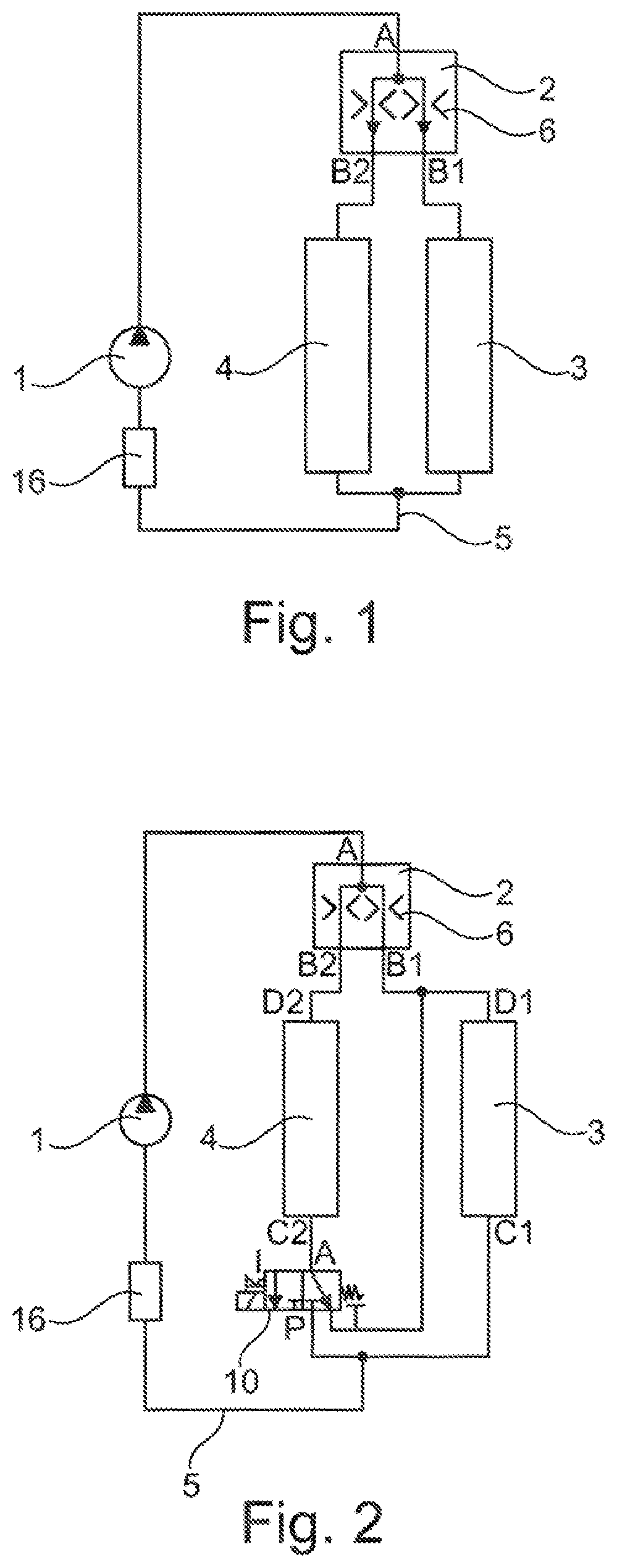
[0023]In FIG. 1, a first exemplary embodiment of the thermal management system according to the disclosure is represented, as used in electrical drive systems or electrical actuators. FIG. 1 shows a coolant circuit with a controllable coolant pump 1, which leads to a coolant distributor implemented as a volumetric flow divider 2. The volumetric flow divider 2 comprises an input A and two outputs B1 and B2. The output B1 leads to a cooling unit 3 for an electric motor, whereas the output B2 leads to a cooling unit 4 for the power electronics. The outputs C1, C2 of the cooling units 3, 4 for the electric motor and the power electronics are merged, so that only one channel 5 is fed back via a vehicle radiator 16 to the coolant pump 1. The cooling units 3, 4 absorb the heat output by the power electronics and the electric motor, whereas the vehicle radiator 16 outputs heat losses to the surroundings.

[0024]A mul...


PUM


Abstract

A thermal management system for an electric drive system, preferably for a vehicle, includes an electric drive including an electric motor and power electronics. The electric motor and the power electronics are integrated in a cooling circuit and are cooled by a coolant circulating in the cooling circuit. The coolant is circulated by a coolant pump. In the case of a variable thermal management system, the electric motor and the power electronics are in spatial contact with respective cooling units. The cooling units of the electric motor and of the power electronics are arranged parallel to each other and an electrically controlled coolant distributor is positioned between the coolant pump and the cooling units which coolant distributor has two outlets. One outlet leads to the cooling unit of the electric motor and one outlet leads to the cooling unit of the power electronics and the outlets of the cooling units are merged into a channel and led back to the coolant pump.

Description

[0001]The disclosure concerns a thermal management system for an electrical drive system, preferably for a vehicle, in which the electrical drive comprises an electric motor and power electronics, wherein the electric motor and the power electronics are incorporated within a cooling circuit and are cooled by a coolant circulating in the cooling circuit, wherein the coolant is circulated by a coolant pump.BACKGROUND[0002]From DE 10 2004 006 730 A1 and DE 10 2011 085 750 A1, methods for detecting damage to a coupling are known, with which in particular the temperature generation in the coupling is considered to apply protective measures in the event of excessive temperatures. The actuator system comprising the coupling, which contains an electric motor and power electronics that actuate the electric motor, comprises a coolant circuit, which in particular cools the power electronics. In this case, the coolant circuit is integrated within a cooling cover of the power output stage, where...

Claims


Application Information

Patent Timeline
Patent Type & Authority Patents(United States)
IPC IPC(8): B60K11/02B60K1/00
CPCB60K11/02B60K1/00B60K2001/003B60Y2306/05H05K7/20936
Inventor GRAMANN, MATTHIASREITH, JOCHENFABER, JUERGENGRAMANN, NICOLAI
Owner SCHAEFFLER TECH AG & CO KG
Why Eureka
Try Eureka