
Method and system for real-time motion artifact handling and noise removal for ToF sensor images

a technology of timeofflight and sensor images, applied in image enhancement, image analysis, instruments, etc., can solve the problems of unreliable depth measurement along object boundaries in dynamic scenes, image corruption, and limited linear motion approach, so as to avoid the risk of spatial artifact propagation, reduce noise, and increase integration time

Active Publication Date: 2022-01-04
IEE INT ELECTRONICS & ENG SA
View PDF16 Cites 0 Cited by
  • Summary
  • Abstract
  • Description
  • Claims
  • Application Information

AI Technical Summary

Benefits of technology

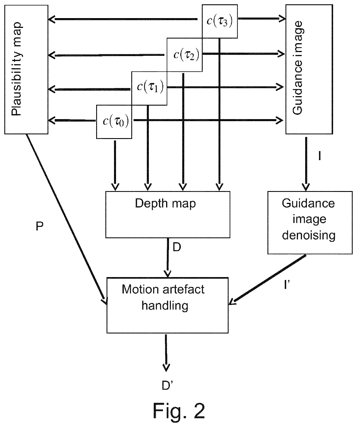
[0069]An advantage of the invention, at least in embodiments, is in addressing the motion artifact from depth map in real time. The object shape is extracted from one of the 4 phase-shifted amplitudes selected according to a criteria taking into account, e.g., the image SNR and edges contrast. This phase-shifted amplitude is used as guidance image for an edge preserving de-noising filter in order to reconstruct the depth of the objects degraded by motion artifact. In the prior art, motion correction is either[0070]a. performed pixel per pixel, without taking into account spatial correlation of the depth map, and usually creating other artifact like noise increase when the depth is corrected, or[0071]b. corrected by spatial analysis using pixel correspondence method between the four phase-shifted amplitudes, but not compatible with real-time application (dense optical flow based methods).
[0070]a. performed pixel per pixel, without taking into account spatial correlation of the depth map, and usually creating other artifact like noise increase when the depth is corrected, or
[0071]b. corrected by spatial analysis using pixel correspondence method between the four phase-shifted amplitudes, but not compatible with real-time application (dense optical flow based methods).
[0072]A further advantage, at least in embodiments, is in edge preserving spatial de-noising of depth map. The guidance image is filtered by means of a dedicated edge preserving de-noising filter. The noise reduction of the guidance image is transferred to the depth map in the motion artifact suppression stage. In the prior art, spatial de-noising is applied to the depth map directly. A spatial de-noising of the depth map requires ideally the depth map to be cleaned from artifacts (motion artifact, flying pixel artifact, . . . ) before being de-noised by an edge preserving filter to avoid the risk of spatial artifact propagation. In the proposed method, the depth map is de-noised by transferring the reduction of noise from the selected processed phase-shifted amplitude image. Phase-shifted amplitudes do not suffer from artifact like the depth map does, and as a consequence, object edges are usually better defined (no flying pixels).
[0073]A further advantage, at least in embodiments, is in the selection of a guidance image to reconstruct the border of moving objects in the depth map. A guidance image is defined as one of the 4 phase-shifted amplitudes. From the 4 phase-shifted amplitude images, the best guidance image is selected using a quality criterion, or a combination of criteria, taking into account, at minimum, the edge contrast and image SNR.
[0074]A further advantage, at least in embodiments, is in the process of the guidance image to reduce noise and remove texture. This image requires a dedicated processing

Problems solved by technology

Those scenes captured by the camera may be either static or dynamic, and in the latter case the images may be corrupted by motion artifacts occurring at moving object boundaries.
However and in practice, unreliable depth measurements arise along object boundaries in dynamic scenes, especially when fast movements are involved.
However, their approach is restricted to linear motion within the range of the camera field-of-view.
However, this method is only applicable to those ToF cameras for which the integration time is divided in two stages, i.e., phase-shifted image pairs are recorded simultaneously.
Consequently, the method requires three optical flow calculations which makes the method non practical for real-time application.
However, real-time performance remains an issue.
A problem with known methods is how to address the motion artefact due to moving objects in the scene, in particular how achieve robust detection of corrupted depth pixels due to motion artefact or saturation.
A further problem is how to achieve real-time performance, enabling for further processing, e.g., gesture recognition or head pose estimation.
A further problem with known methods is how to achieve noise removal whilst preserving edges.
A further problem is how to select a guidance image to reconstruct the boundaries of moving objects.
A further problem with known methods is how to achieve noise and texture removal from the guidance image.
In the prior art, motion correction is eithera. performed pixel per pixel, without taking into account spatial correlation of the depth map, and usually creating other artifact like noise increase when the depth is corrected, orb. corrected by spatial analysis using pixel correspondence method between the four phase-shifted amplitudes, but not compatible with real-time application (dense optical flow based methods).

Method used


Image

  • Method and system for real-time motion artifact handling and noise removal for ToF sensor images
  • Method and system for real-time motion artifact handling and noise removal for ToF sensor images
  • Method and system for real-time motion artifact handling and noise removal for ToF sensor images

Examples


Embodiment Construction

[0085]As used herein, the “images” or “image signals” may be analog or digital, and may be subject to conventional analog or digital filtering.

[0086]Where references are made herein to steps, operations or manipulations involving “images”, etc., these are implemented, where appropriate, by means of operations upon electronically processable representations (e.g. captured stills of video frame signals, bitstream video data, MPEG files or video streams, PC-video, or any other capturable or viewable image data format) of such “images”.

[0087]Where references are made herein to steps, operations or manipulations involving “images”, “image signals” or “image data”, these may be implemented, where appropriate, by means of software controlled processor operations, hardware circuitry or any suitable combination of these.

[0088]While the present invention is suitably embodied in a computer system, it may be incorporated in an adaptor, an image processor, or any other equipment located between ...


PUM


Abstract

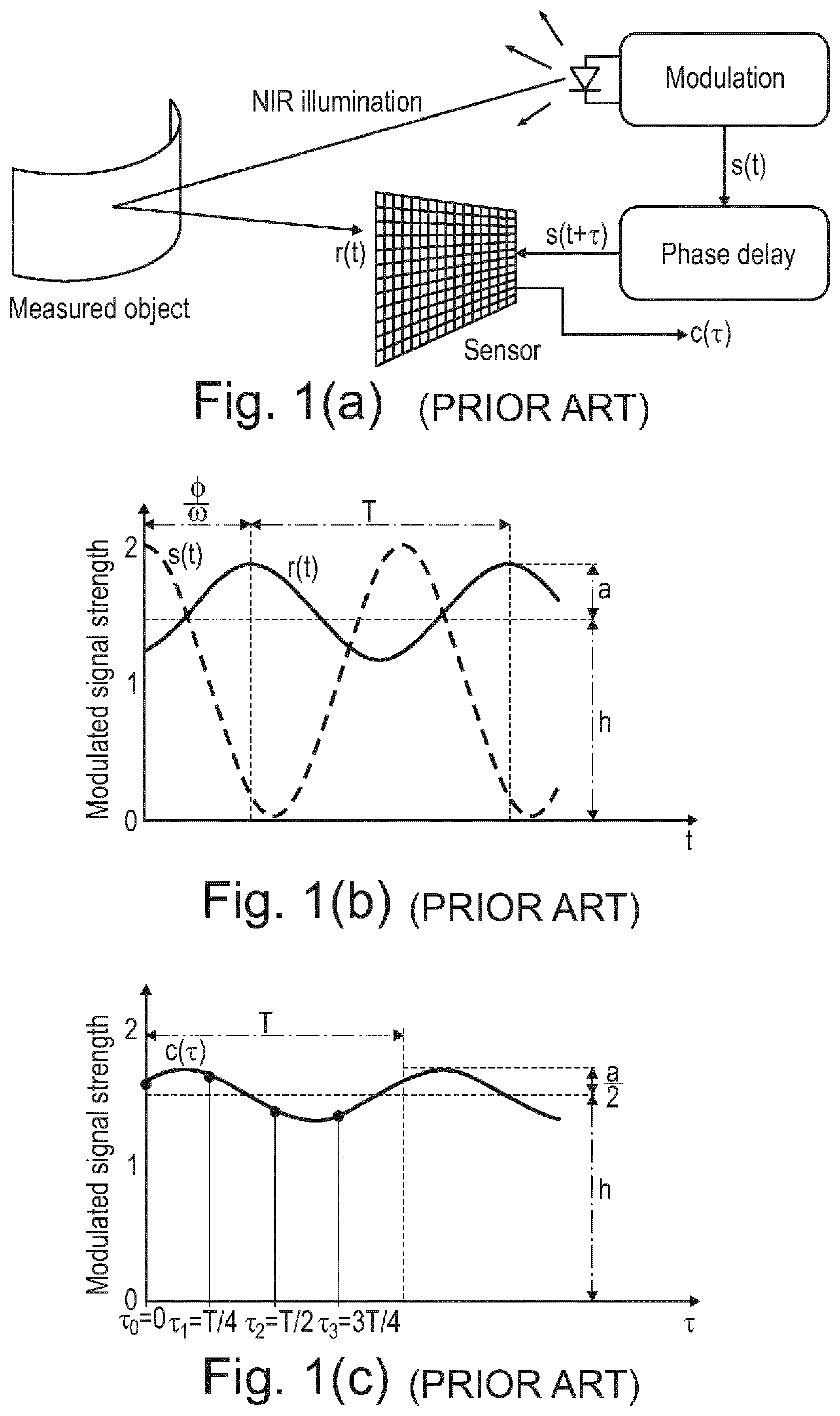
A method and system for real-time motion artifact handling and noise removal for time-of-flight (ToF) sensor images. The method includes: calculating values of a cross correlation function c(τ) at a plurality of temporally spaced positions or phases from sent (s(t)) and received (r(t)) signals, thereby deriving a plurality of respective cross correlation values [c(τ0), c(τ1), c(τ2), c(τ3)]; deriving, from the plurality of cross correlation values [c(τ0), c(τ1), c(τ2), c(τ3)], a depth map D having values representing, for each pixel, distance to a portion of an object upon which the sent signals (s(t)) are incident; deriving, from the plurality of cross correlation values [c(τ0), c(τ1), c(τ2), c(τ3)], a guidance image (I; I′); and generating an output image D′ based on the depth map D and the guidance image (I; I′), the output image D′ comprising an edge-preserving and smoothed version of depth map D, the edge-preserving being from guidance image (I; I′).

Description

TECHNICAL FIELD[0001]The present invention relates to image processing, and more particularly to a method and system for real-time motion artifact handling and noise removal for Time-of-Flight (ToF) sensor images.BACKGROUND ART[0002]There are a range of fields and applications in which accurate distance calculation by means of a ToF sensor (e.g. camera) is required. Those scenes captured by the camera may be either static or dynamic, and in the latter case the images may be corrupted by motion artifacts occurring at moving object boundaries.[0003]Typical applications involving accurate depth measurements are human-computer interaction, in which fast hand segmentation for gesture recognition is sought, and automotive related applications, where occupancy classification, head pose estimation and / or environment perception is to be performed. Other applications will be apparent to the skilled person.[0004]ToF cameras based on demodulation lock-in pixels estimate depth from the phase-shi...

Claims


Application Information

Patent Timeline
Patent Type & Authority Patents(United States)
IPC IPC(8): G01S7/48G01S7/4865G01S17/36G01S7/493G01S17/894G06T5/00
CPCG01S7/4866G01S7/493G01S17/36G01S17/894G06T5/002G06T5/003G06T2207/10028G06T2207/20182G06T2207/20192G06T11/008
Inventor SCHOCKAERT, CEDRICGARCIA BECERRO, FREDERICMIRBACH, BRUNO
Owner IEE INT ELECTRONICS & ENG SA
Learn More