
Linear vibration motor

a linear vibration and motor technology, applied in mechanical vibration separation, dynamo-electric machines, electrical apparatus, etc., can solve the problems of increased manufacturing cost, low finished product yield, increased process difficulty,

Active Publication Date: 2022-02-01
AAC TECH PTE LTD
View PDF9 Cites 0 Cited by
  • Summary
  • Abstract
  • Description
  • Claims
  • Application Information

AI Technical Summary

Benefits of technology

The present patent provides a linear vibration motor with a foam damping mechanism using a blocking piece. This mechanism simplifies the structure of the vibration unit, reduces manufacturing costs, and improves the yield of the motor. The blocking piece compresses the foam to provide mechanical damping, and the foam supports the blocking piece to simplify the vibration unit. This results in a more efficient and reliable motor.

Problems solved by technology

However, fixing the foamed cotton on the mass block in the related art not only increases the process difficulty of the mass block, but also increases the manufacturing cost, and the finished product yield is low.

Method used


Image

  • Linear vibration motor
  • Linear vibration motor
  • Linear vibration motor

Examples


Embodiment Construction

[0012]The present disclosure will hereinafter be described in detail with reference to several exemplary embodiments. To make the technical problems to be solved, technical solutions and beneficial effects of the present disclosure more apparent, the present disclosure is described in further detail together with the figure and the embodiments. It should be understood the specific embodiments described hereby is only to explain the disclosure, not intended to limit the disclosure.

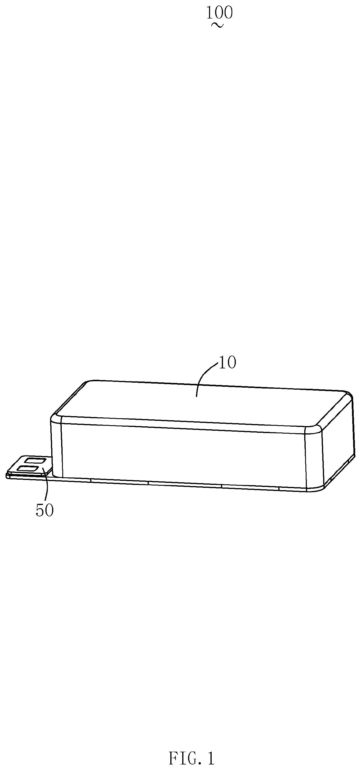
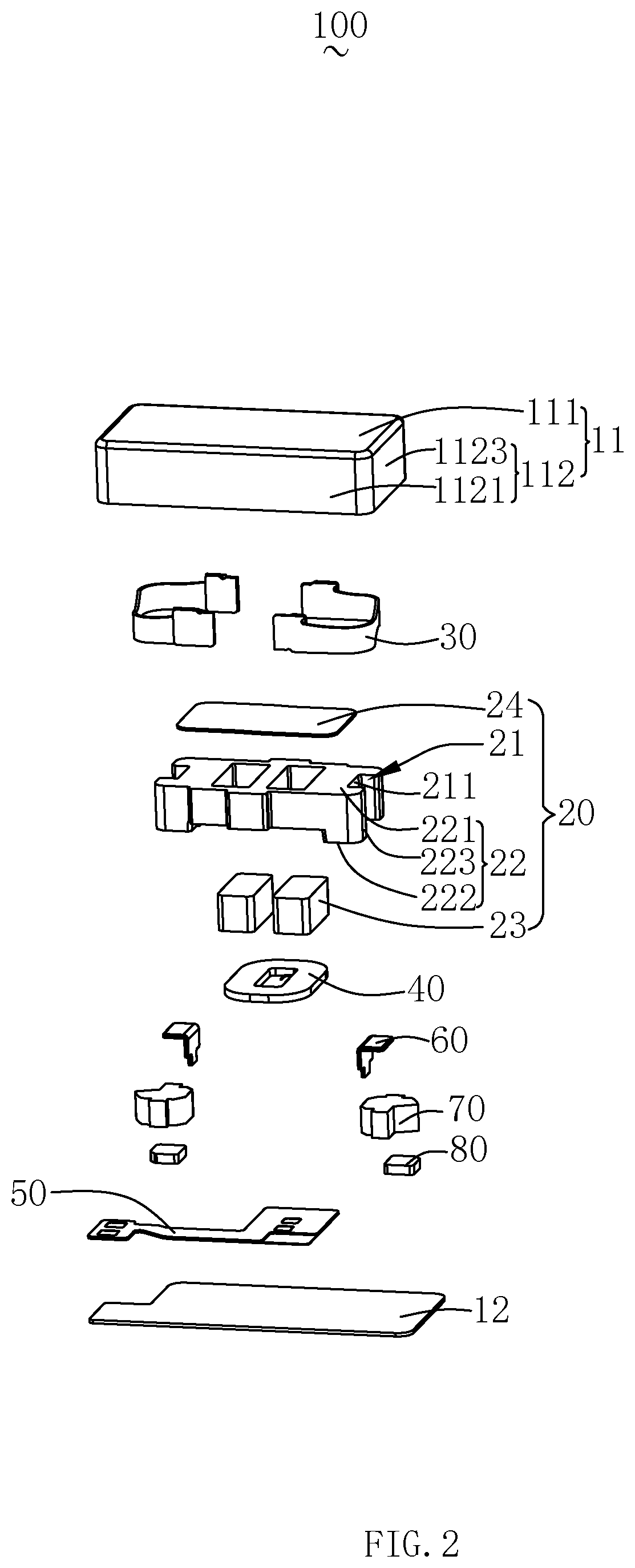
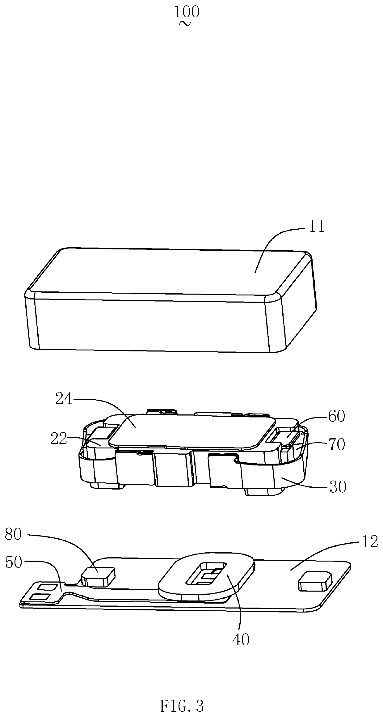
[0013]Please also refer to FIG. 1 to FIG. 3, wherein FIG. 1 is a schematic diagram of the three-dimensional structure of the linear vibration motor of the present disclosure, FIG. 2 is a decomposition structure diagram of the linear vibration motor shown in FIG. 1, and FIG. 3 is a partial decomposition structure diagram of the linear vibration motor. The present disclosure provides a linear vibration motor 100, which comprises a shell 10 having a housing space, a vibration unit 20 housed in the housing spac...


PUM


Abstract

The present disclosure provides a linear vibration motor. The linear vibration motor comprises a shell having a housing space, a vibration unit housed in the housing space, an elastic member suspending the vibration unit in the housing space, and a driving unit driving the vibration unit to vibrate. The vibration unit comprises a housing portion recessed inwardly on two sides perpendicular to the vibration direction. The housing portion includes respective inner walls constituting the housing portion. The linear vibration motor further includes a blocking piece housing in the housing portion and fixedly connected to the inner wall, and a foamed cotton fixedly connected to the blocking piece and at least partially received in the housing portion, the blocking piece carrying and supporting the foamed cotton, and the blocking piece cooperating with the foamed cotton to limit the displacement of the vibration unit in the vibration direction.

Description

FIELD OF THE DISCLOSURE[0001]The present disclosure relates to vibration motors, and more particularly to linear vibration motors.DESCRIPTION OF RELATED ART[0002]A linear vibration motor is a device that converts electrical energy into mechanical energy by using the principle of electromagnetic force generation, and the linear vibration motor is usually installed in a portable mobile device to generate vibration feedback, such as vibration of a mobile phone or vibration feedback of a game player.[0003]In the related art, the linear vibration motor comprises a shell having a housing space, a vibration unit housed in the housing space, an elastic member for suspending the vibration unit in the housing space, and a driving unit for driving the vibration unit to vibrate. The vibration unit comprises a mass block accommodated in the housing space and a magnetic assembled with the mass block. In order to control the vibration range of the vibration unit, a plurality of foamed cotton is us...

Claims


Application Information

Patent Timeline
Patent Type & Authority Patents(United States)
IPC IPC(8): H02K33/16B06B1/04
CPCH02K33/16B06B1/045B06B1/04
Inventor TAO, FENGLING, FANGHUAWANG, JUNSHENGPU, XIAOFENG
Owner AAC TECH PTE LTD
Learn More