
Shale shaker buffer wear item and method for use

a technology of wear-reducing barrier and shaker, which is applied in the direction of filtration separation, separation process, borehole/well accessories, etc., can solve the problems of major limiting factor of the integrity and longevity of individual shale shaker functionality, wear, corrosion, corrosion of metal, etc., and achieve the effect of preventing excessive wear of the shaker basket deck flats

Active Publication Date: 2022-03-08
HERRINGTON BRETT
View PDF6 Cites 1 Cited by
  • Summary
  • Abstract
  • Description
  • Claims
  • Application Information

AI Technical Summary

Benefits of technology

The buffer effectively extends the lifespan of shaker screens and deck flats, reducing the frequency of replacements, minimizing equipment damage, and enhancing drilling fluid separation efficiency, thereby improving productivity and safety while lowering overall costs.

Problems solved by technology

Therefore, it has become more and more evident that the durability of (and wear experienced by) shale shakers and shale shaker baskets across all industries has become, and will persist, as a major limiting factor of the integrity and longevity of individual shale shakers' functionality.
What is more, in many environments in which vibratory separators and shale shakers are used, these metal parts are subjected to harsh conditions that result in wear, erosion, rust, and corrosion of metal due to the drilling mud introduced into the shaker baskets as well as a multitude of harsh environmental factors.
The fluids themselves can be a mixture of various chemicals in liquid (e.g. a water-based solution, an oil-based solution, or a synthetic based solution) and can be both caustic to handle and expensive to manufacture.
The removal of the greatest quantity of coarse solids (as well as successive processing of finer-grained solids) on the first circulation of mud from the well is important before any subsequent reintroduction into the well can be initiated as drilling solids reintroduced into the well have the potential to be detrimental the functional components of a drilling equipment and adversely affect well integrity, rig productivity, production costs and worker safety.
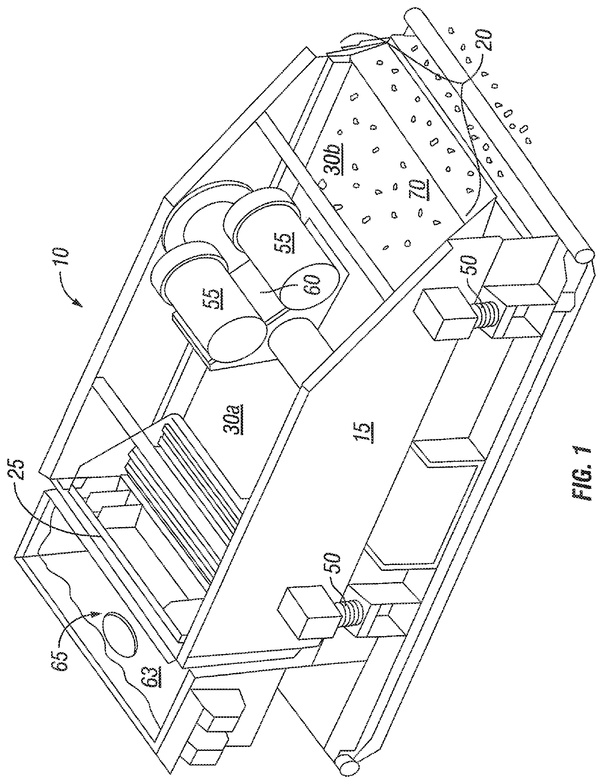
Yet, the primary rate limiting step can be pin-pointed to the primary site of vibration and thus friction—the shale shaker basket (consisting of the deck / flat and shale shaker screen).
In addition, shale shaker baskets, and the eventual wear experienced at the basket, garners a second, yet correspondingly important, albeit less conveniently amendable area of remediation.
Although replacement is less frequent, removing a worn basket and replacing that basket with a new basket nonetheless becomes inevitable at the incursion of great expense.
The logistics of basket replacement and semi-permanence of the basket itself, creates an untenable cost not only in terms of actual replacement but also in terms of disruptions in production.
Wear itself results in improperly functioning shale shakers that ultimately allow unwanted solids to translocate across defective screens (or bypass screens altogether) to cause increased percentages of low gravity / fine solids build-up in the active mud system (by both worn screens, worn basket decks or the intersection at the separation of communication of screens to shaker basket).
The unwanted materials that accumulate in the system subsequently cause increased wear on pumps, down hole motors, and bottom hole assemblies which increasingly jeopardize the integrity of the well bore leading to decreased safety, increased cost of the drilling and ultimately decreased petroleum production overall.
This process is costly, sometimes averaging over 50% the cost of a new basket.
The wear on the basket causes drilling contractors to experience nonproductive time leading to wasted resources.
The inability to operate the shaker results in (1) increased cost to fix the shaker basket, (2) increased cost due to idle machinery and lost production materializing in (3) an overall increased cost of the well production and the oil that is derived therefrom.

Method used


Image

  • Shale shaker buffer wear item and method for use
  • Shale shaker buffer wear item and method for use
  • Shale shaker buffer wear item and method for use

Examples


Embodiment Construction

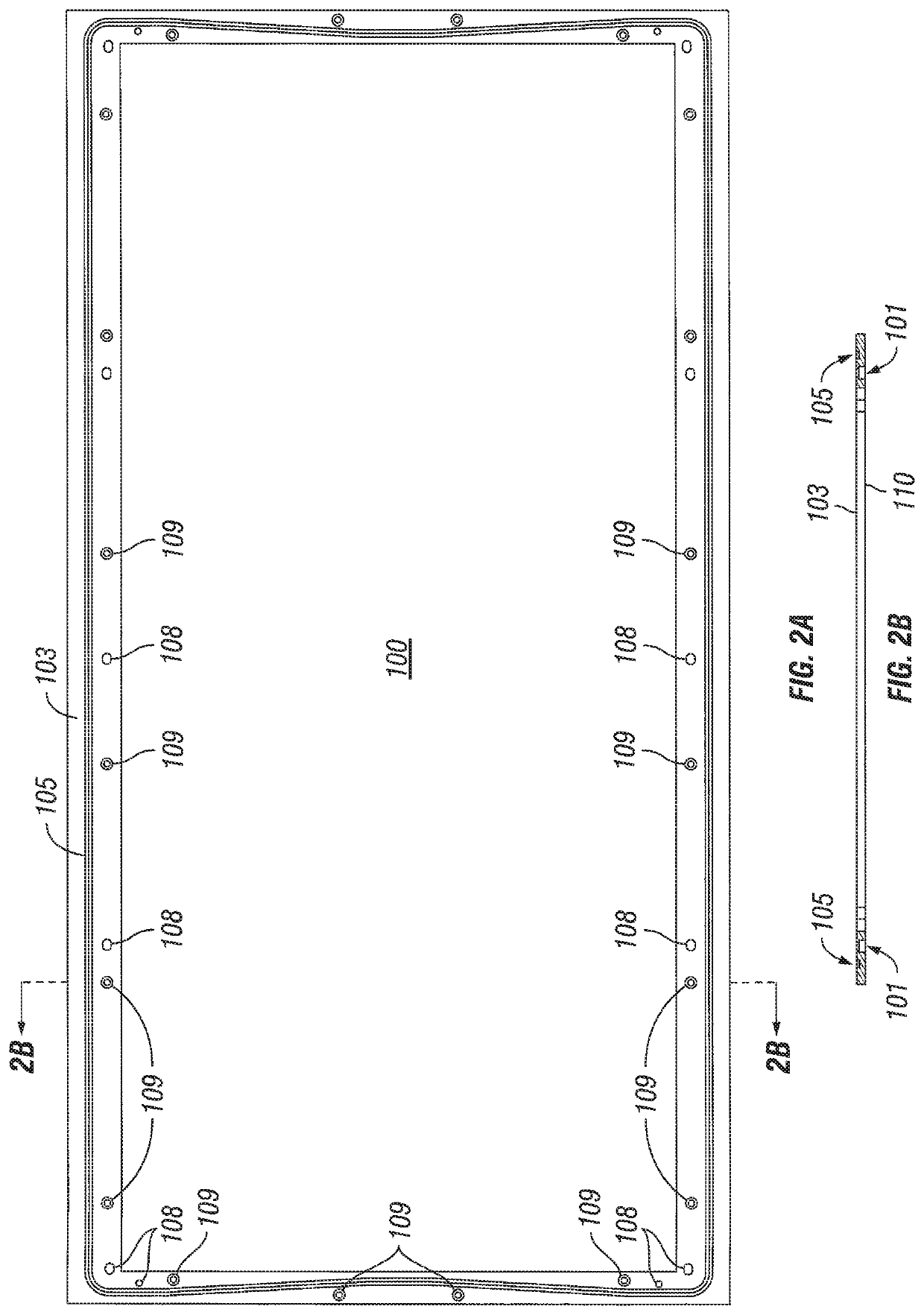
[0025]Detailed description of the preferred embodiments of the invention are disclosed and described below. Yet, each and every possible feature, within the limits of the specification, are not disclosed as various permutations are envisioned to be within the purview and contemplation of inventor and understood to those having skill in the art. It is therefore possible for those having skill in the art to practice the disclosed invention while observing that certain placement and spatial arrangements are relative and capable of being arranged and rearranged at various points about the present invention that nonetheless accomplishes to remedy one or more of the infirmities as outlined and discussed above in the field of solids control and management. Patently, the size and shape of certain features may be expanded or narrowed to accommodate each individual shaker basket and may be customizable to suit various and variable screen sizes and shapes while maintaining the underlying funct...


PUM

PropertyMeasurementUnit
thicknessaaaaaaaaaa
sizesaaaaaaaaaa
gravityaaaaaaaaaa

Abstract

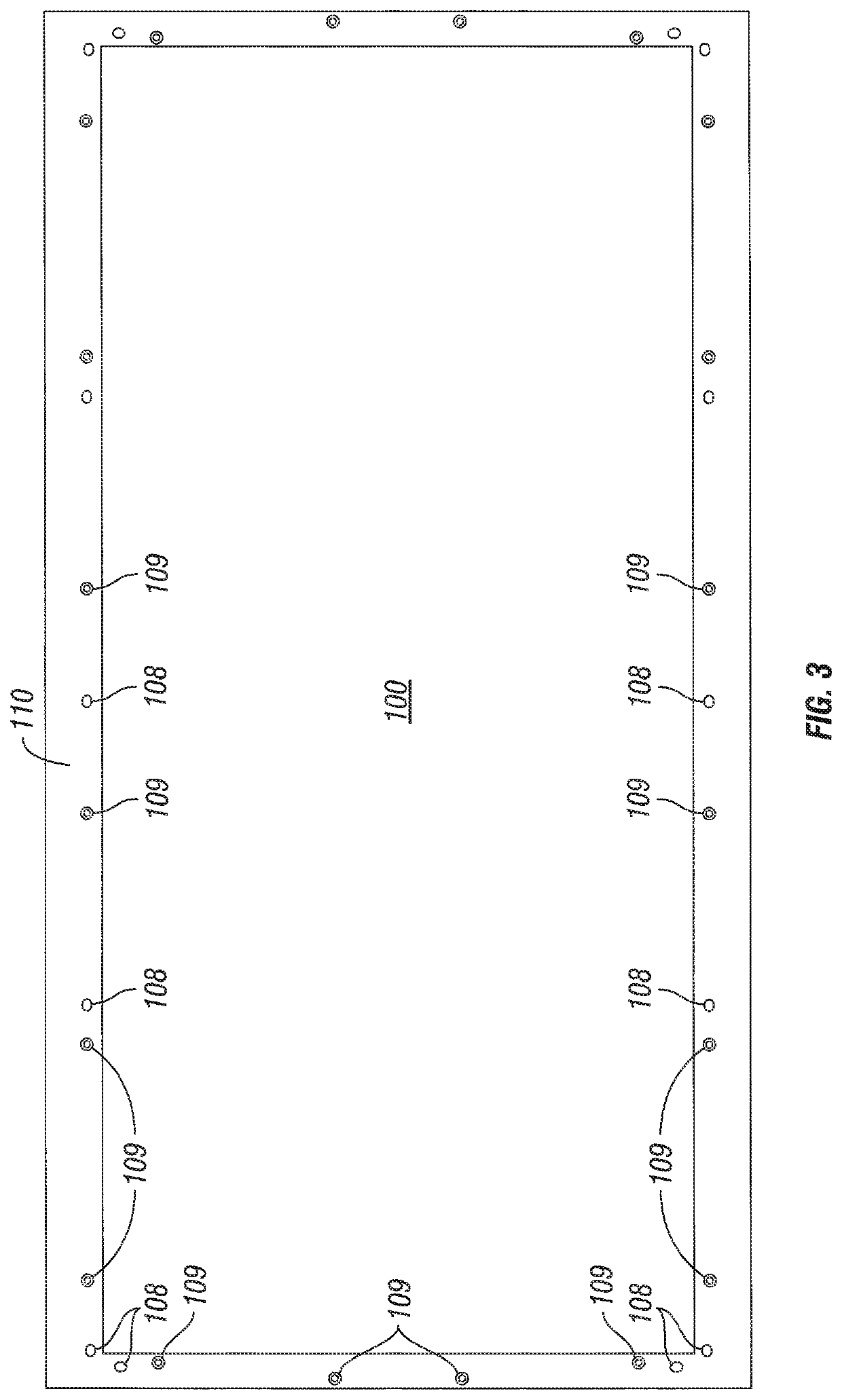
A shale shaker buffer and wear reduction barrier, placed between a shale shaker filter screen, shale shaker wear items and a shale shaker deck of a shale shaker for the prevention of vibratory and friction-induced wear that is reversibly adhered, placeable and replaceable to a shale shaker filter screen, shale shaker wear items and a shale shaker deck of a shale shaker basket to decrease wear on a shale shaker's functional components, singularly and in combination. The buffer and wear reduction barrier that is the present invention serves the additional function of a solids control barrier as an operable seal between a shale shaker filter screen, wear items and deck of a shale shaker to obviate entrance of solids into mud pits via wear induced areas of separation between shale shaker filter screen, wear items and a deck of a shale shaker.

Description

BACKGROUNDField of the Invention[0001]The present invention is directed to a buffer and wear reduction barrier, placed between shale shaker expendable wear items and the deck flat of a shale shaker basket for the prevention of friction-induced wear, generally. Specifically, being placed between wear items and a shaker screen deck of a shale shaker, the apparatus and method of use are designed to extend the life of shale shaker filtering screens, wear items and shale shaker deck flats to which they are attached thereby extending the operational life of the entire shale shaker basket.Description of the Related Art[0002]As reported by the American Petroleum Institute (API), it is estimated that for every foot of well drilled about 1.2 barrels of waste drilling mud is generated. The impact of drilling waste on the efficiencies and cost of drilling activities has become a major concern for the energy production industry. Waste control and associated potential detrimental environmental ef...

Claims


Application Information

Patent Timeline
Patent Type & Authority Patents(United States)
IPC IPC(8): B07B1/46E21B21/06B01D33/03
CPCB07B1/469E21B21/065B01D33/0353B07B2201/04B07B1/4627
Inventor HERRINGTON, BRETT
Owner HERRINGTON BRETT
Learn More