High-density optical module system

a high-density, optical module technology, applied in the field of optical module devices and system communications, can solve the problems of difficulty in combining all the individual adaptors in a crowded 1u space, low and limited number of connector ports in conventional optical modules

Active Publication Date: 2022-05-17
OPTIWORK
View PDF4 Cites 2 Cited by
  • Summary
  • Abstract
  • Description
  • Claims
  • Application Information

AI Technical Summary

Benefits of technology

[0010]An object of the present invention is to provide a high-density optical module system with the maximum numbers of pre-loading or pre-connection of the fiber optic adaptors to the connector terminals of the optical module to facilitate the connections of the adaptors.
[0011]A further object of the present invention is to provide a high-density optical module system that optimizes the use of the space of the plurality of connector ports.
[0012]Still another object of the present invention is to provide a high-density optical module system with easy access to the plugs for making and breaking connector connections without applying specific tools.
[0013]Still another object of the present invention is to provide a high-density optical module system to facilitate the positioning and coupling between the adaptors to the connector terminals of the optical module to facilitate the connections of the adaptors.

Problems solved by technology

However, the numbers of the connector ports are usually low due to the limited spacing of the front sides of the optical modules.
However, it is quite challenging to couple all the individual adaptors in a crowded 1U space.
The conventional optical modules have limitations on providing the maximum numbers of connector ports.
As more connector ports are paced within the limited 1U space, it creates problems for technicians to access and remove the connectors by using their hands.
The arrangement of ports further creates difficult tasks for the technicians to access or remove the connectors within the crowded rows or columns of ports.

Method used


Image

  • High-density optical module system
  • High-density optical module system
  • High-density optical module system

Examples


Embodiment Construction

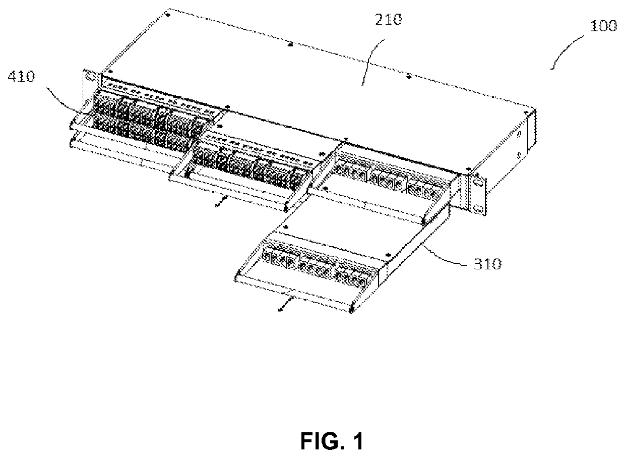
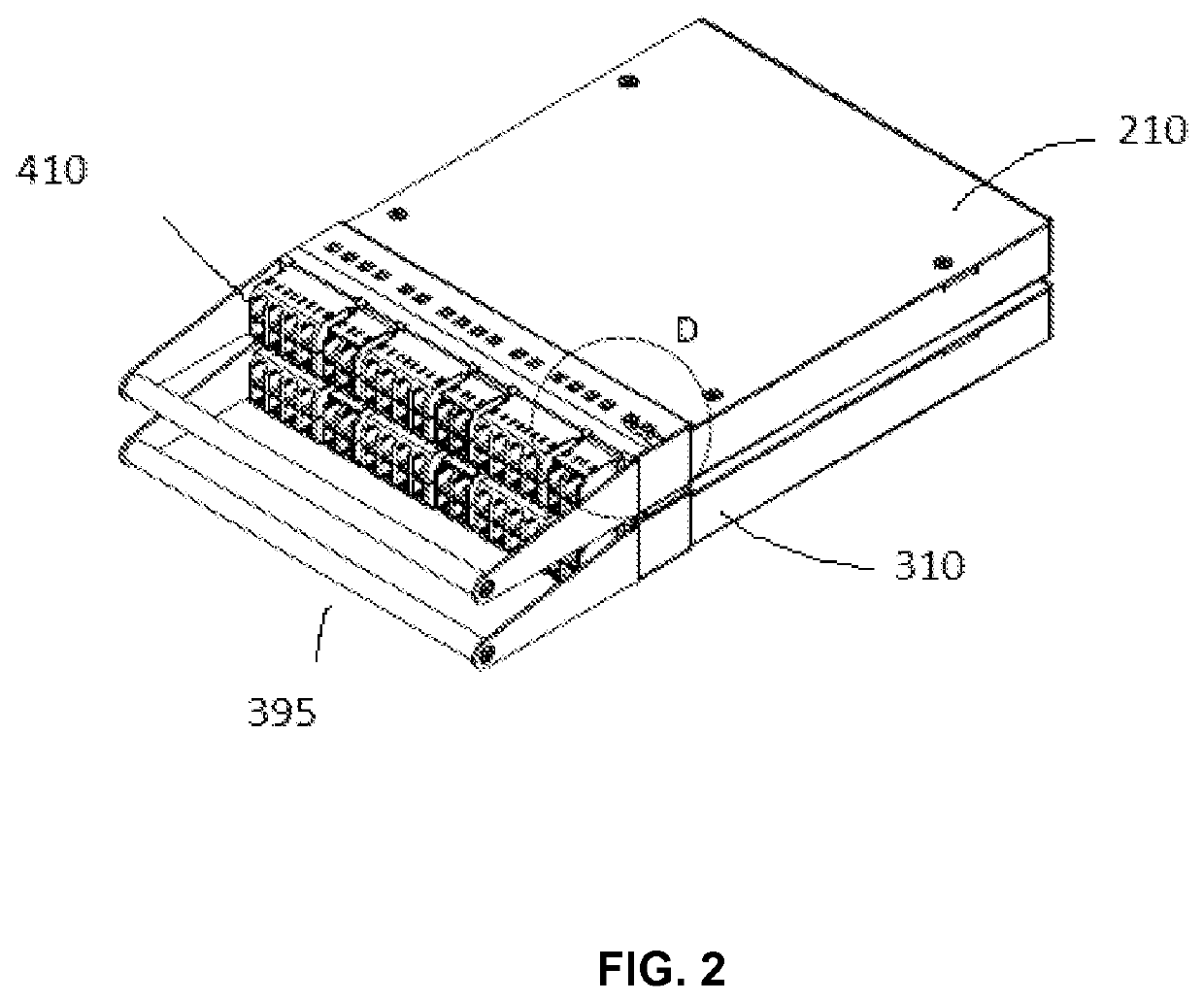
[0029]Disclosed herein is a high density optical module system 200 illustrated in FIGS. 1-11. The optical module system 100 is used for centralizing and supporting the connections of a plurality of adaptors at a single rack mounted panel. The optical module system 100 can also be used in wall mounting applications and outside plant closure applications.

[0030]The high-density optical module system 100 comprises a multi-tier housing assembly 210, the sliding tray assembly 310, and a plurality of multi-port modules 410. The single sliding tray assembly 310 is engaged inside the housing assembly 210 and can be fully extracted outwardly or extended inwardly from the housing assembly 210 by the user's hand operation. The plurality of multi-port modules 410 are coupled with the adaptors for connections. As shown in FIG. 1, the high-density optical module system 100 contains a 2-tier housing assembly 210, which accommodates two sliding tray assemblies 310 engaged therein. Further as shown i...


PUM


Abstract

A high-density optical module system of the present invention comprises: a multi-tier housing assembly, multiple sliding tray assemblies engaged inside each of the multi-tier housing assembly and is moveable inwardly and outwardly within the multi-tier housing assembly with the handle bar; and a multiple rows of the multi-port modules arranged in horizontal arrays containing plural ports connected to the cable adaptors, wherein the multi-port modules are fastened into the sliding tray assembly. The height of the high-density optical module system is approximately 1RU (19 inches) containing at least 216 LC or 108 SC multiple connector ports.

Description

CROSS-REFERENCE TO RELATED APPLICATIONS[0001]This application is related to U.S. Design patent application Ser. No. D / 520,627 entitled “High-Density Optical module System” and filed concurrently herewith.FIELD OF THE INVENTION[0002]The present invention generally relates to a device and a system to fiber-optic communications. More specifically, the present invention relates to optical module device and system communications, which facilitates access to manage fiber optic connectors, adapters, and ports, and maximize the space utilization thereof.BACKGROUND OF THE INVENTION[0003]In the management of fiber-optic connector communications, a plurality of fiber-optic cables are interconnected through connectors or adaptors. The front side of the optical module provides for the use of connecting and routing circuits for energy transmission adaptors, such as the adaptors or the fiber optic cable adaptors. The rear side of the optical module provides for connections to the long wires or cab...

Claims


Application Information

Patent Timeline
Patent Type & Authority Patents(United States)
IPC IPC(8): G02B6/44
CPCG02B6/4455G02B6/4452
Inventor MA, YANYANHAN, TAOZHU, CHUANXING
Owner OPTIWORK
Why Eureka
Try Eureka