LED lighting device having opposed irregular lenslet arrays with planar facets

a technology of planar facets and lenslet arrays, which is applied in the direction of lighting and heating apparatus, semiconductor devices for light sources, instruments, etc., can solve the problems of increasing the manufacturing cost and complexity of the lenslet arrangement, affecting the color uniformity of the light, and affecting the appearance of objects, etc., to achieve the effect of improving the beam forming capability, reducing manufacturing costs, and improving color uniformity

Active Publication Date: 2022-05-17
SIGNIFY HLDG BV
View PDF18 Cites 0 Cited by
  • Summary
  • Abstract
  • Description
  • Claims
  • Application Information

AI Technical Summary

Benefits of technology

[0018]It has been found that the combination of irregularly (tessellated) lenslet arrays in which individual lenslets are aligned (paired) with a corresponding lenslet in the opposing array with planar (flat) facets at the pockets between lenslets in at least one of the lenslet arrays causes, upon imaging a collimated light source, a uniform halo effect around the imaged main beam, especially when the number of lenslets in the array is high, e.g. at least 100. Such a halo effect is considered aesthetically acceptable in many application domains including LED lighting. This is because such planar facets ‘truncate’ the lenslet area as part of the base of the lenslet is covered by a planar facet, which eliminates (or at least reduces) edge artefacts caused by these pockets and causes the generation of an amount of uncontrolled light. Another way to describe the lenslets arrangement with facets is that in between at least three adjacent, mutually touching lenslets relatively deep pockets are formed, the bottom of these pockets being said planar facets via which the sharp ends of the bottoms are truncated thus reducing the undesired artefacts caused by deep pockets, but generating the uncontrolled light. This uncontrolled light generates a background light level around the main beam, which due to the irregular nature of the tessellation pattern, combines into the uniform halo. The second lenslet array creates images of the convex portions of the lenslets of the first lenslet array, thereby improving the definition of the main beam, in particular when the first lenslet array faces the collimated light source.
[0022]Preferably, the planar facets lie in the same virtual plane in order to maximize the uniformity of the halo effect. By defining the height of the virtual plane, i.e. the amount of facet material over the facet intersections, the amount of cut-off lenslet surface area can be controlled, e.g. to control the intensity of the halo.
[0029]At least the first lenslet array may be integral to the collimator, e.g. to limit the total number of components in the optical arrangement and / or to reduce manufacturing cost.
[0030]According to yet another aspect, there is provided a lighting device comprising the optical arrangement of any of the herein described embodiments and at least one LED light source positioned relative to the collimator such that the collimator collimates the light of the at least one LED light source and projects said collimated light onto the lenslet arrangement. Such a lighting device, e.g. a spot light, exhibits improved beam forming capability in the far field, e.g. improved color uniformity and reduced visibility of edge artefacts due to the presence of the lenslet arrangement in its optical arrangement.

Problems solved by technology

Non-uniform light sources such that e.g. light emitting diode (LED) arrays and LEDs of different colours may hence cause artefacts visible in the resulting light beam and beam spot when combined with a collimator.
This is undesirable in applications where an approximately constant intensity with a relative hard cut-off is preferred.
However, it is not straightforward to create such an image in the far field that is relatively free of artefacts.
In particular, when trying to generate a round beam profile, this may be attempted with circular lenslets, but circular lenslets cannot form a tessellated lenslet array and the spaces between the circular lenslets in the array, e.g. an array in which the circular lenslets are arranged in a hexagonal arrangement, cause artefacts in the far field image.
Such artefacts may be suppressed by covering these spaces with an opaque (masking) material, but this requires a complex additional processing step, which increases the manufacturing cost and complexity of the lenslet arrangement.
Instead of circular lenslets, polygonal lenslets may be deployed that can form a tessellated lenslet array, but such tessellations cannot form a round beam.
Such tessellations provide average round patterns but with poorly defined pattern edge gradients because many images of protruding polygon corners extend beyond the spherical beam target shape.
In lighting optics, in spite of the large number, e.g. several hundreds or thousands, of lenslets in each array, such protruding corners become clearly visible as a sharply defined corner or as a colour-separated protrusion (in case of colour mixing), which is undesirable.

Method used


Image

  • LED lighting device having opposed irregular lenslet arrays with planar facets
  • LED lighting device having opposed irregular lenslet arrays with planar facets
  • LED lighting device having opposed irregular lenslet arrays with planar facets

Examples


Embodiment Construction

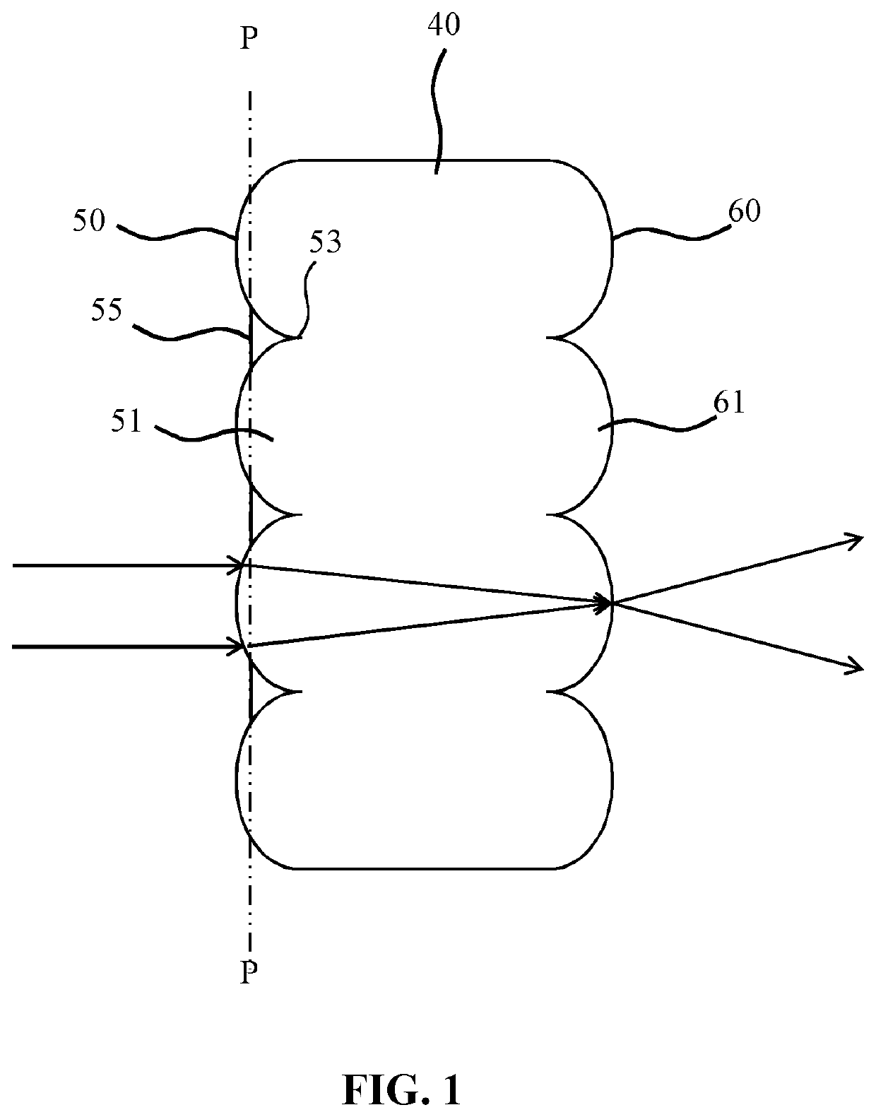
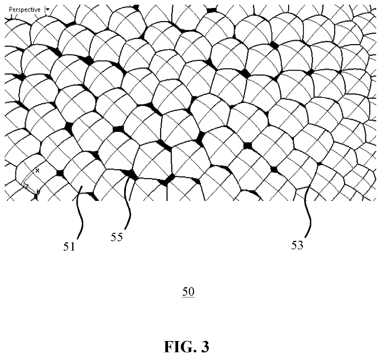
[0041]It should be understood that the Figures are merely schematic and are not drawn to scale. It should also be understood that the same reference numerals are used throughout the Figures to indicate the same or similar parts.

[0042]FIG. 1 schematically depicts a lenslet arrangement 40 according to an embodiment of the present invention. The lenslet arrangement 40 comprises a first lenslet array 50 and a second lenslet array 60. The first lenslet array 50 comprises a tessellated pattern of first lenslets 51 and the second lenslet array 60 comprises a tessellated pattern of second lenslets 61. The first lenslets 51 and the second lenslets 61 face away from each other in opposite directions, e.g. along the optical axis of the lenslet arrangement 40. In FIG. 1, the lenslet arrangement 40 is made as a single body comprising the first lenslet array 50 and the second lenslet array 60 on opposite surfaces of the single body, e.g. an integrating lenslet plate. This has the advantage that t...


PUM


Abstract

A lighting device includes at least on LED light source, ca collimator, a first lenslet array of lenslets tessellated in an irregular pattern, and a second array of lenslets tessellated in the same irregular pattern as the first array of lenslets, such that each of the lenslets in the first array is aligned with a corresponding one of the lenslets in the second array. The first array further includes a plurality of transmissive planar facets covering an intersection between lenslet.

Description

CROSS-REFERENCE TO PRIOR APPLICATIONS[0001]This application is the U.S. National Phase application under 35 U.S.C. § 371 of International Application No. PCT / EP2017 / 078065, filed on Nov. 2, 2017, which claims the benefit of European Patent Application No. 16198564.3, filed on Nov. 14, 2016. These applications are hereby incorporated by reference herein.FIELD OF THE INVENTION[0002]The present invention relates to an integrating lenslet arrangement including a first lenslet array of lenslets tessellated in an irregular pattern; and a second lenslet array of further lenslets tessellated in said irregular pattern, each further lenslet being aligned with one of said lenslets.[0003]The present invention further relates to an optical arrangement including such a lenslet arrangement.[0004]The present invention further relates to a lighting device comprising such an optical arrangement.[0005]The present invention further relates to a luminaire including such a lighting device.BACKGROUND OF T...

Claims


Application Information

Patent Timeline
Patent Type & Authority Patents(United States)
IPC IPC(8): F21V5/04G02B19/00G02B3/00F21Y115/10
CPCG02B19/0061F21V5/04G02B3/0068G02B19/0028F21Y2115/10G02B3/0043G02B3/0056G02B3/0062
Inventor DROSS, OLIVERVISSENBERG, MICHEL CORNELIS JOSEPHUS MARIE
Owner SIGNIFY HLDG BV
Why Eureka
Try Eureka