Stacked lamination rotor

a technology of stacked lamination and rotor, which is applied in the direction of stator/rotor body manufacturing, magnetic circuit rotating parts, magnetic circuit shape/form/construction, etc. it can solve the problems of limited lamination lateral dimensions, limited monolithic rotor thickness, and other half of the system cost, so as to maximize the utilization of the flywheel enclosure

Active Publication Date: 2022-06-14
AMBER KINETICS
View PDF7 Cites 2 Cited by
  • Summary
  • Abstract
  • Description
  • Claims
  • Application Information

AI Technical Summary

Benefits of technology

[0014]In certain embodiment, a rotor shape is used that improves over a standard circular disc shape by maximizing the utilization of a flywheel enclosure by the rotor.
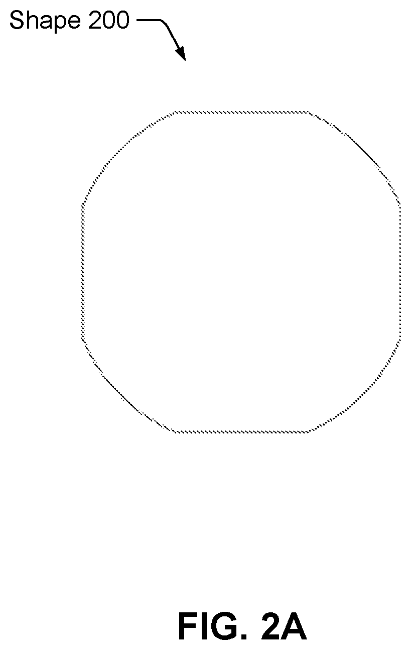
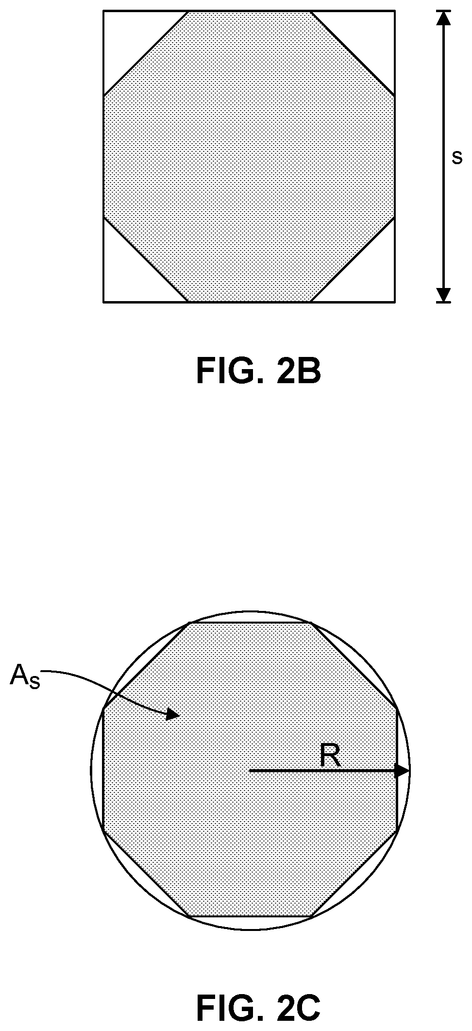
[0015]Embodiments of rotor shapes are described that enable laminations in a stacked lamination rotor to be advantageously joined. In certain embodiments, a circular shape that has protruding scallops, referred to as a scalloped circular shape, is disclosed. The laminations include one or more holes through which axial bolts pass for the purpose of joining and fastening the laminations. In other embodiments, an octosquare shape is used that allows through holes near each of the vertices without incurring a performance limiting stress riser.

Problems solved by technology

Thus, the other flywheel components constitute the other half of the system cost.
The maximal peak stress may be limited by a failure criteria related to material yield or ultimate stress, or may be limited by a cyclic fatigue constraint.
Lamination lateral dimensions are only limited by available supply widths of material stock, i.e. the coil width.
Basically, the ubiquitous, continuous rolling processes replaces the one-off forging step; (2) Monolithic rotor thickness is limited by the hardenability of the steel alloy that is used.
For a 6-inch-thick rotor to achieve the same strength levels as a 2 mm-thick lamination, a substantially more expensive steel alloy must be used.
Defects oriented perpendicular to the radial or hoop directions will form cracks and grow more quickly than defects parallel to the hoop and radial directions.
Monolithic forged rotors may have defects oriented parallel with the rotor axis, which is the most vulnerable orientation for fatigue crack growth in such a structure.
Although these are standardized testing processes, the demands are substantial, since an inspection error can be catastrophic.
In applications intended for many 10,000's of full swing stress cycles, each corresponding to a full deep cycle of the flywheel energy storage system, stress swing is usually practically limited by cyclic fatigue.

Method used


Image

  • Stacked lamination rotor
  • Stacked lamination rotor
  • Stacked lamination rotor

Examples


Embodiment Construction

[0038]The invention now will be described more fully hereinafter with reference to the accompanying drawings, which form a part hereof, and which show, by way of illustration, specific exemplary embodiments by which the invention may be practiced. This invention may, however, be embodied in many different forms and should not be construed as limited to the embodiments set forth herein; rather, these embodiments are provided so that this disclosure will be thorough and complete, and will fully convey the scope of the invention to those skilled in the art. Among other things, the invention may be embodied as methods, processes, systems, or devices. The following detailed description is, therefore, not to be taken in a limiting sense.

Introduction

[0039]A laminated rotor is constructed by stacking many laminations where each of the laminations in the stack has the same shape and the same orientation relative a center axis. For example, a 300 mm thick rotor requires 150 laminations of 2 m...


PUM


Abstract

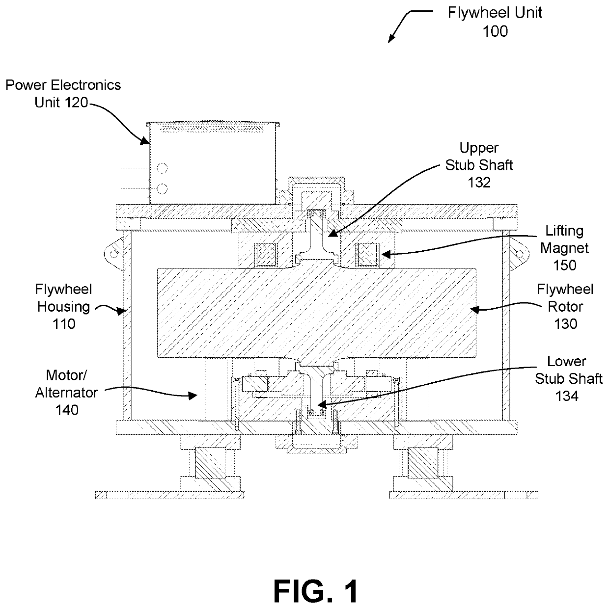
The invention is a flywheel rotor that includes a number of adjacent laminations, stacked one on top of another, where each of the laminations has the same shape and is rotationally symmetric around a center axis, and where the shape is substantially circular and includes a plurality of protrusions on the circumference, and each of the laminations includes at least one hole for at fastening bolts to pass through. The invention typically includes an endplate at each end of stack of laminations and one of the two endplates attaches to a stubshaft.

Description

BACKGROUND1. Field of Art[0001]This description generally relates to energy storage using flywheels. Specifically, it pertains to the design of flywheel rotors comprised of stacked laminations.2. Description of the Related Art[0002]Modern energy storage rotors applied in multi-hour utility scale applications, as well as in short duration power applications such as Uninterruptible Power Supply (UPS) settings, are commonly built either with composite fiber wound rotors, or from steel. When addressing the multi-hour discharge applications that occur in utility applications, and also in some commercial / industrial settings, optimizing rotor cost is a central objective.[0003]The cost of a flywheel rotor may constitute in the range of 50% of the manufactured system cost. Thus, the other flywheel components constitute the other half of the system cost. And many of these system costs scale with rotor volume and / or mass. lifting, Thus, reducing rotor mass and volume is a premium concern in fl...

Claims


Application Information

Patent Timeline
Patent Type & Authority Patents(United States)
IPC IPC(8): H02K1/30H02K15/16H02K15/02H02K7/02
CPCH02K1/30H02K7/025H02K15/02H02K15/165H02K7/04F16F15/30F16F2226/04Y02E60/16
Inventor SANDERS, SETH R.GAISER, KYLE B.OLSEN, GREGHOLLOWAY, MARK J.HITCHCOCK, ROGER NELSONTENNESSEN, PETER THOMASSENESKY, MATTHEW K.CHIAO, EDWARD YOUNGCONOLLY, DARLENE W.RODEWALD, KEENAN WILLIAM
Owner AMBER KINETICS
Why Eureka
Try Eureka