
Thermal management for thermal cyclers using air tubes

a technology of thermal cycler and air tube, which is applied in the construction details of electrical apparatus, refrigeration components, lighting and heating apparatus, etc., to achieve the effect of minimizing failure of the board, minimizing the temperature fluctuation of the thermal board assembly, and reducing or eliminating the routing of cables

Active Publication Date: 2022-06-28
BIO RAD LAB INC
View PDF7 Cites 0 Cited by
  • Summary
  • Abstract
  • Description
  • Claims
  • Application Information

AI Technical Summary

Benefits of technology

[0007]Due to the relatively high impedance of the heat sink, a proper airflow ratio should be maintained between the heat sink and the electronics board assembly. In addition, due to direct contact between the heat pump and thermal board assembly, some of the heat generated by high electrical current in the heat pumps is transferred to the thermal board assembly which is ultimately dissipated to outside. Thus, the thermal solution described-above can effectively reduce the heat generated by the heat pump and the control circuit board assembly concurrently. In another aspect, this approach can also minimize non-uniformity of the sample block of the heat pump by reduction of the heat generated in the high current circuitry of the PCBs at the top surface of the heat pump. The conformable nature of this approach permits its use even in applications where space is limited. Another benefit of this approach is that it allows the one or more the cooling fans to be positioned elsewhere (for example, at the back, underneath or at the sides of the instrument) which leaves space in the front of the instrument available for other auxiliary components, such as LCD, cables, etc.
[0009]Another object of the present invention is the provision of maintaining stability or minimizing temperature fluctuation of the thermal board assembly in order to minimize failure of the board even at the temperature-elevated environment.
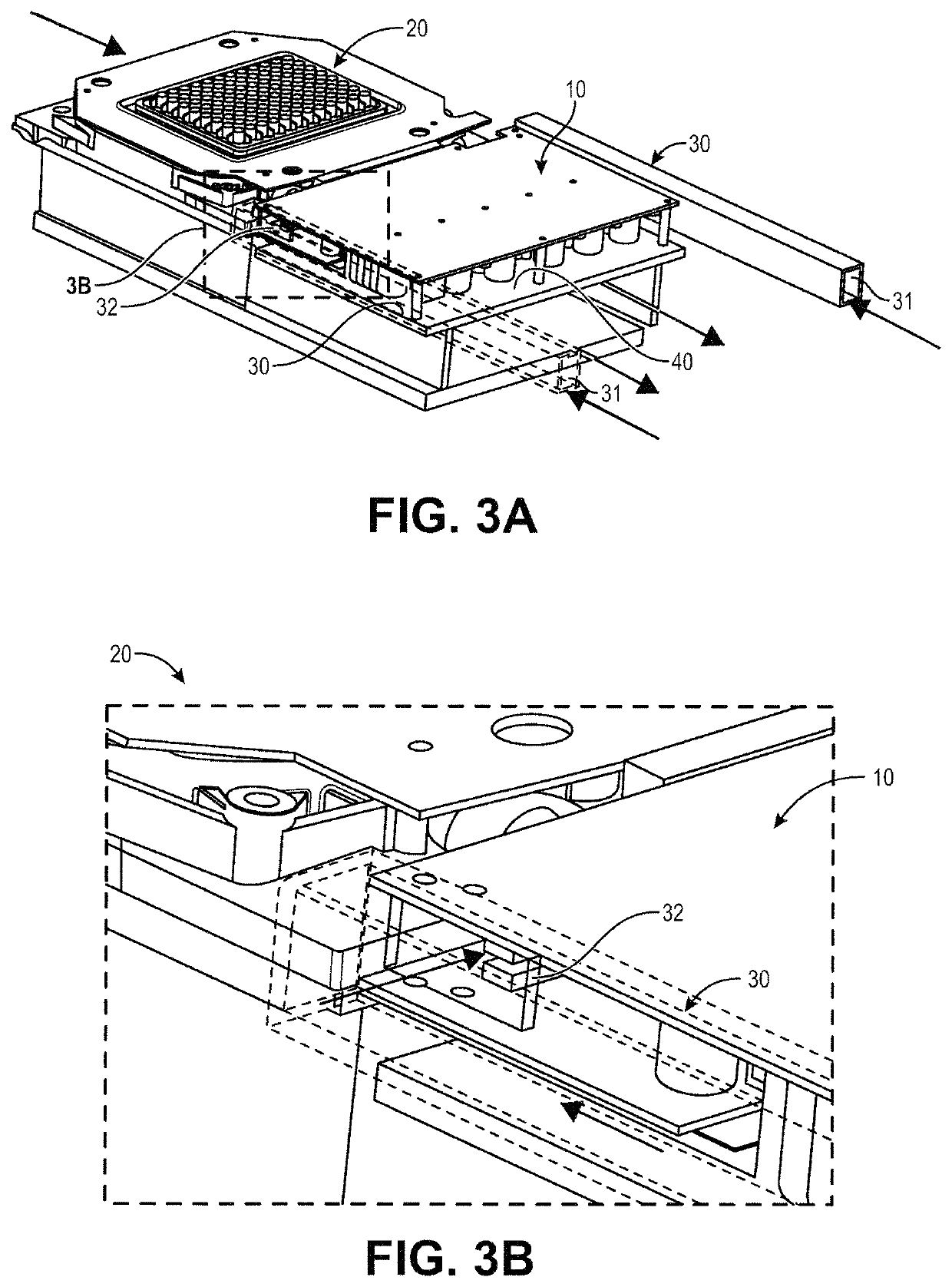
[0010]Another technical advantage of the system is that the thermal boards can be directly coupled with the heat pump, thereby reducing or eliminating any cable routing that might obstruct airflow. This approach also allows building of an assembly that includes a heat pump, thermal boards, fans, and air tubes or conduits as a module. Providing this assembly as a module is convenient for both manufacturing and service as the module can be removed for repair or replaced.
[0014]In some embodiments, the cooling system is relatively planar, which contrasts with cooling systems designed for test tubes, and which allows for reduced size as compared to certain conventional systems having additional external cooling components attached thereto.

Problems solved by technology

In addition, due to direct contact between the heat pump and thermal board assembly, some of the heat generated by high electrical current in the heat pumps is transferred to the thermal board assembly which is ultimately dissipated to outside.

Method used


Image

  • Thermal management for thermal cyclers using air tubes
  • Thermal management for thermal cyclers using air tubes
  • Thermal management for thermal cyclers using air tubes

Examples


Embodiment Construction

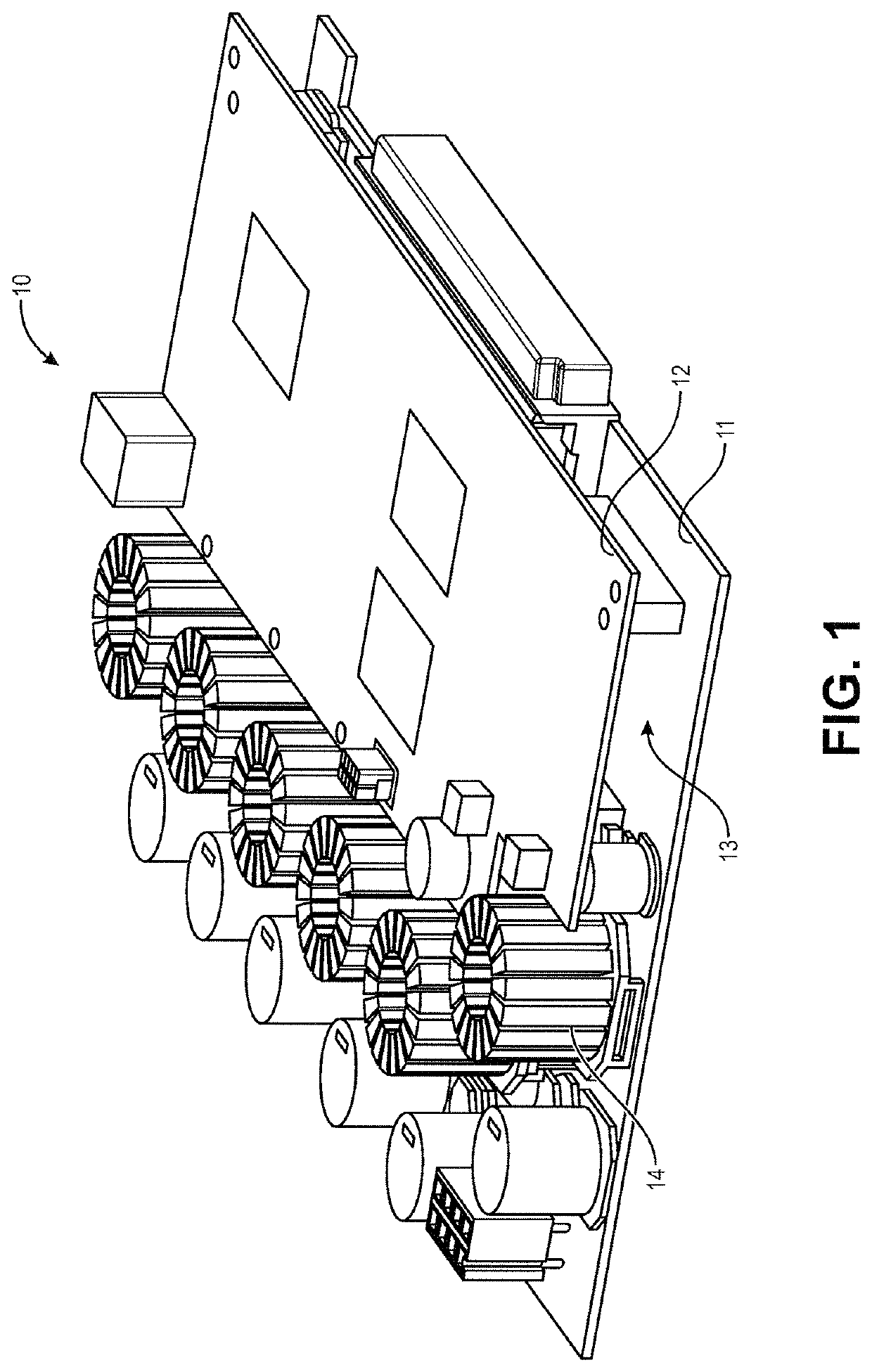
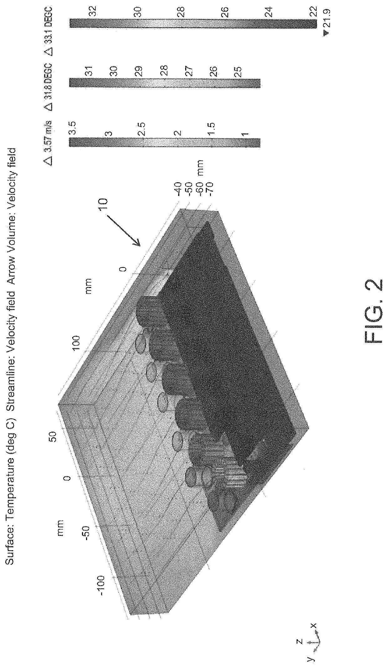
[0029]In one aspect, the present invention provides a thermal management assembly that dissipates the heat from an electronics board control assembly while simultaneously or concurrently controlling the temperature of a heat sink of a heat pump for thermocycling. An example of an electronic board assembly suitable for use in such an assembly is shown in FIG. 1. The electronics board assembly 10 is configured with a thermal controller and driver board for controlling thermal cycling. The electronics board assembly 10 includes two PCBs 11, 12 with a space 13 therebetween. At least one PCB 11 includes high-powered electrical components 14. As can be seen in FIG. 2, which shows a thermal simulation of the electronic board assembly 10 during thermal cycling operation, the high powered components 14 can generate significant heat during operation such that cooling of the electronic board assembly is needed. In this embodiment, the electronic board assembly is configured to be directly conn...


PUM


Abstract

A thermal management system that include an electronic circuit boards having at least two circuit boards with a space in between and further includes one or more air tubes or conduits. The electronic circuit board and air tubes are configured for drawing air into the space to facilitate cooling of the electronic circuit board concurrent with cooling of a heat sink of a heat pump connected with the electronic circuit board. The system can further include a partition to isolate airflow from the heat sink from airflow through the electronics circuit board, and can further include one or more interface components for maintaining isolation and control of air flow, improving air intake and / or supporting auxiliary components.

Description

CROSS-REFERENCE TO RELATED APPLICATIONS[0001]The present application claims priority to U.S. Provisional Application No. 62 / 939,419, entitled “THERMAL MANAGEMENT FOR THERMAL CYCLERS USING AIR TUBES” and filed Nov. 22, 2019, the entire contents being incorporated herein by reference for all purposes.BACKGROUND OF THE INVENTION1. Field of the Invention[0002]This invention pertains to thermal management for thermal cycling systems, such as heat pumps and heat sink assemblies.2. Description of the Prior Art[0003]Conventional heat pumps typically include a control unit with an electronics circuit board with electrical components that generate significant heat during thermal cycling of the heat pump. Such system generally utilize independent active cooling features, typically electronics fans, for cooling of the electronics circuit board. In addition, since the electronics can act as heat sources, the circuit board is often located remotely and attached to the heat pump through wires. Thi...

Claims


Application Information

Patent Timeline
Patent Type & Authority Patents(United States)
IPC IPC(8): H05K1/02H05K7/20
CPCH05K1/0272H05K7/20145H05K7/20163H05K7/20209H05K2201/064H05K2201/066F25B49/02F25B2700/2117F25B2600/112Y02B30/70H05K1/0203B01L7/52B01L2300/1844B01L2300/1894
Inventor SADRI, AMIRNIKOLIC, NEVENCULINCO, GABRIELTRAN, THANH-VIKIRCANSKI, NENAD
Owner BIO RAD LAB INC
Learn More