Shoe component and manufacturing method thereof

a technology of shoe components and foaming, applied in the field of shoe components, can solve the problems of poor mechanical strength of foaming shoe components made from eva, such as midsoles, poor durability and compression sets, poor stability of shoe components after injection molding, etc., and achieves the effects of less bore diameter, increased mechanical strength of foaming shoe components, and reduced bore diameter

Active Publication Date: 2022-07-12
FENG TAY ENTERPRISE CO LTD
View PDF18 Cites 0 Cited by
  • Summary
  • Abstract
  • Description
  • Claims
  • Application Information

AI Technical Summary

Benefits of technology

[0006]In view of the above, the primary objective of the present disclosure is to provide a shoe component and a manufacturing method thereof; through the Microcellular foam process with supercritical fluid provided in the present disclosure, the environmental hazard from the conventional chemical foaming process could be improved, and the uneven quality of the conventional foaming products could be improved, too. The foaming products provided in the present disclosure is suitable to be made into several shoe components including midsole, outsole, overlay of upper or sole and insole, but not limited thereto.
[0009]With the aforementioned design, through the Microcellular foam process with supercritical fluid, the foaming shoe component could be made by a physical process, so that the foaming shoe component provided in the present disclosure has a plurality of foaming bores which are dense and uniform, whereby to increase whole mechanical strength of the foaming shoe component. Furthermore, comparing to the conventional foaming shoe component, the foaming shoe component provided in the present disclosure has greater physical properties, such as less bore diameter, greater resilience, less compression set, and greater tear strength.

Problems solved by technology

Though EVA has the aforementioned advantages, the foam shoe component made from EVA, such as a midsole, has poor physical properties; for example, said shoe component is poor in durability and compression set, and said shoe component after injection molding is poor in size stability.
In addition, the process of EVA injection molding, which is a chemical foam process, has cumbersome steps, so that the process is usually time-consuming.
Further, for the process of EVA injection molding needs to add chemical foaming agent and crosslinking agent, such as dicumyl peroxide (DCP), the shoe component containing chemical foaming agent and crosslinking agent is not easy to be decomposed, which is not recyclable, so that EVA is not an environmentally friendly material.
Furthermore, most of chemical foaming agent and crosslinking agent are environmental hormones, which are poisonous to human bodies and the environment.
Besides, in current physical foaming process of shoe components by injection molding, the products are generally formed as flat-shaped foaming bodies, which are not easy to be three-dimensional foaming bodies having curved surfaces, and are not easy to have a volume ratio to the mold being 1:1.
Further, for the evenness of bore size of foaming bodies is difficult to be regulated, the productivity of the foaming shoe components becomes worse.

Method used


Image

  • Shoe component and manufacturing method thereof
  • Shoe component and manufacturing method thereof
  • Shoe component and manufacturing method thereof

Examples


first embodiment

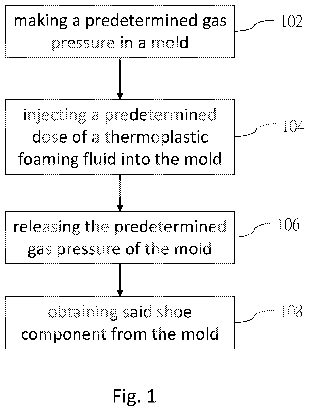
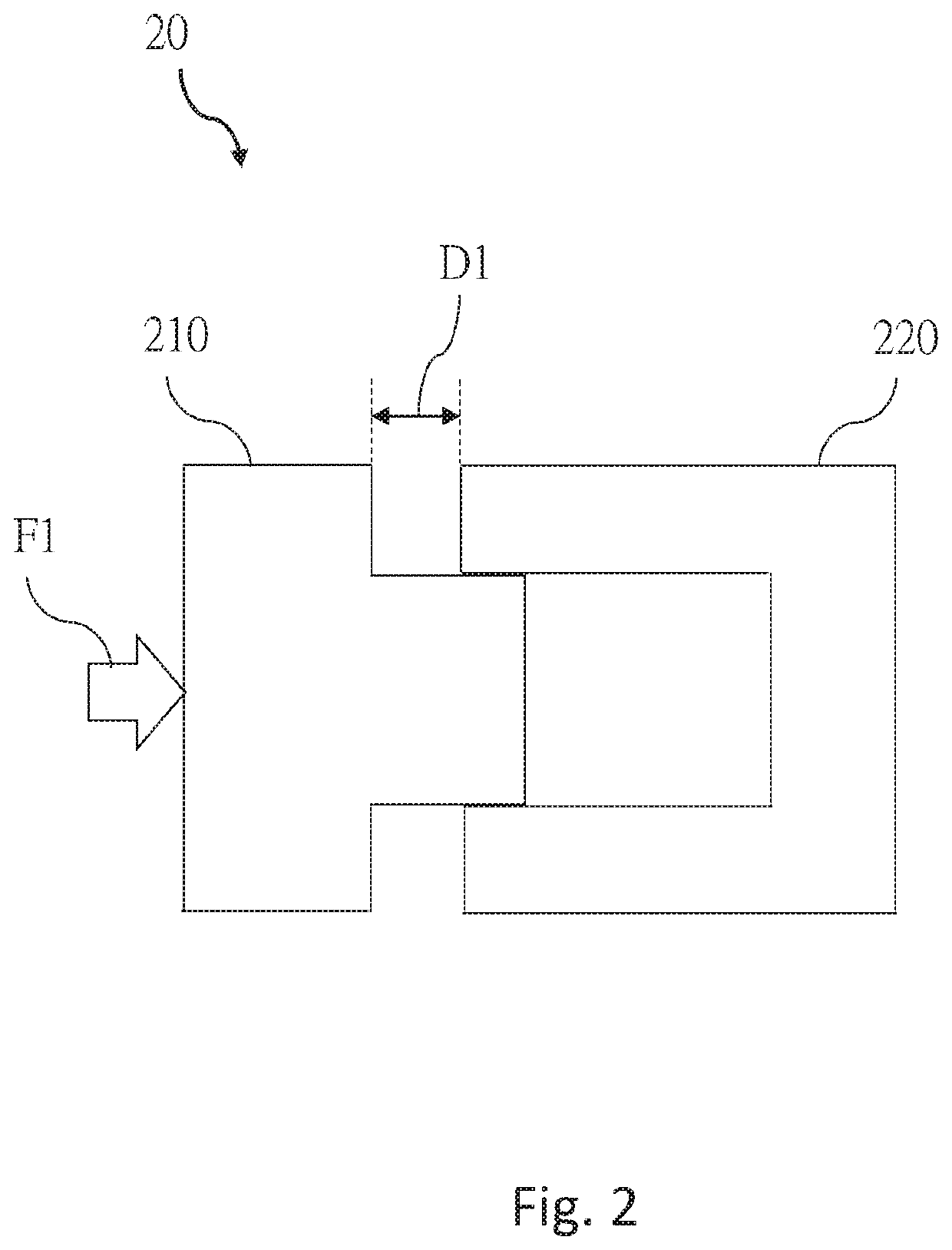
[0030]According to the present disclosure, as shown in FIG. 2 and FIG. 3, the mold 20 includes a first molding member 210 and a second molding member 220, wherein the first molding member 210 and the second molding member 220 are correspondingly mated, and the first molding member 210 can be moved relative to the second molding member 220 by an external force F1. In Step 106 of FIG. 1, the step of releasing the predetermined gas pressure of the mold performs in a process of the first molding member 210 moved from a first position (as shown in FIG. 2) to a second position (as shown in FIG. 3) by the external force F1. In FIG. 2, when the first molding member 210 is at the first position, a shortest distance of the first molding member 210 to the second molding member 220 is defined as a first distance D1. In FIG. 3, when the first molding member 210 is at the second position, a shortest distance of the first molding member 210 to the second molding member 220 is defined as a second d...

second embodiment

[0031]According to the present disclosure, as shown in FIG. 4 and FIG. 5, the mold 20 includes a first molding member 210 and a second molding member 220, wherein the first molding member 210 and the second molding member 220 are correspondingly mated, and the first molding member 210 can be moved relative to the second molding member 220 by an external force F2. In Step 106 of FIG. 1, the step of releasing the predetermined gas pressure of the mold performs in a process of the first molding member 210 moved from a first position (as shown in FIG. 4) to a second position (as shown in FIG. 5) by the external force F2. Through the first molding member 210 is pulled toward the second molding member 220, a foaming space in the mold 20 could be increased, so as to decrease the specific gravity of the foaming body.

[0032]In FIG. 4, when the first molding member 210 is at the first position, a shortest distance of the first molding member 210 to the second molding member 220 is defined as a...


PUM

PropertyMeasurementUnit
gas pressureaaaaaaaaaa
diametersaaaaaaaaaa
gas pressureaaaaaaaaaa

Abstract

A shoe component includes a foam member including a thermoplastic material and a mixed material mixed to each other, wherein the weight percentage of the thermoplastic material is 90 wt % to 99 wt %, and the weight percentage of the mixed material is 10 wt % to 1 wt %. A manufacturing method of the shoe component is also disclosed herein.

Description

BACKGROUND OF THE INVENTION1. Technical Field[0001]The present disclosure relates generally to a shoe component and a manufacturing method thereof, and more particularly to a Microcellular foam shoe component and a manufacturing method thereof.2. Description of Related Art[0002]Generally, components of a foam shoe component usually includes ethylene vinyl acetate (EVA) and thermoplastic polyurethane (TPU), wherein EVA naturally has properties of lightweight, soft, shockproof and heat insulation, and the price of EVA is lower than that of TPU, so a midsole of a shoe is usually made from EVA.[0003]Though EVA has the aforementioned advantages, the foam shoe component made from EVA, such as a midsole, has poor physical properties; for example, said shoe component is poor in durability and compression set, and said shoe component after injection molding is poor in size stability. In addition, the process of EVA injection molding, which is a chemical foam process, has cumbersome steps, so...

Claims


Application Information

Patent Timeline
Patent Type & Authority Patents(United States)
IPC IPC(8): B29C44/58A43B13/04B29C44/02B29C44/34B29C44/42B29K101/12B29K105/04B29K509/00B29L31/50
CPCB29C44/588A43B13/04B29C44/02B29C44/3403B29C44/42B29K2101/12B29K2105/041B29K2509/00B29K2995/0088B29L2031/504B29D35/12C08J9/0066C08J9/32C08J2300/22C08J2375/04C08J2377/00C08J2367/00C08J2203/22C08J9/0085B29C44/3496B29C44/586
Inventor YANG, TSUNG-LINCHANG, YU-TA
Owner FENG TAY ENTERPRISE CO LTD
Why Eureka
Try Eureka