System for managing at least one sub-assembly of an electric battery

a technology for electric batteries and sub-assemblies, which is applied in the direction of battery/fuel cell control arrangement, secondary cell servicing/maintenance, electric devices, etc., can solve the problems of significant excess weight of the system, difficult to maintain the integrity of analogue or digital signals relative to sources of electromagnetic disturbance of signals, and the number of wired connections comprised in the system to be reduced, and the effect of low cos

Active Publication Date: 2022-07-26
EM MICROELECTRONIC-MARIN
View PDF6 Cites 0 Cited by
  • Summary
  • Abstract
  • Description
  • Claims
  • Application Information

AI Technical Summary

Benefits of technology

[0012]One advantage of the present invention resides in the fact that each communication circuit associated with a power storage cell is configured such that it transposes, over a carrier frequency having a value that is greater than or equal to 1 GHz, the data to be received and to be transmitted, and in the fact that the management system includes, for the one or for each sub-assembly, a loss cable connecting the power storage cells of this sub-assembly. The loss cable is coupled by capacitive coupling to the communication circuit of each power storage cell. This prevents any galvanic contact between the communication circuits and the loss cable, and thus allows the number of wired connections comprised in the system to be reduced, moreover since there is only one loss cable per sub-assembly of the battery.
[0013]Furthermore, such a carrier frequency having a value of greater than or equal to 1 GHz allows very high transmission rates to be obtained, allowing for transmission or receipt of data in very little time, with a high communication frequency and a very high throughput. This allows for real-time or near real-time cell management monitoring with a very high throughput. Thanks to the management system according to the invention, approximately one hundred power storage cells of an electric battery, for example, can thus be monitored at a speed exceeding 1000 Hz, such a speed being 10 to 100 times greater than the speed required, with management systems of the prior art, to monitor the same number of power storage cells. This allows for the more comprehensive and optimal management of the electric battery, in particular the consumption thereof, in all phases of use of the battery.
[0014]Finally, another advantage of the system according to the invention is that it does not produce electromagnetic radiation inside the one or more sub-assemblies of the electric battery. This prevents the appearance of electromagnetic compatibility issues, and further prevents the need to design antenna systems specific to the battery. More specifically, in the present invention, the transmission or reception of data within each sub-assembly of the electric battery takes place via a capacitive coupling, in guided radio wave propagation mode, and not via radiofrequency radiation in a free field. Such a propagation mode by guided radio waves further guards against sources of electromagnetic disturbance, such as engines for example.
[0015]Advantageously, the value of the carrier frequency is substantially equal to 5.7 GHz. This value of 5.7 GHz allows a significant bandwidth to be obtained, allowing the transmission rate and the real-time or near real-time management monitoring to be optimised, while retaining simple and inexpensive electronic circuits. In particular, this carrier frequency value of 5.7 GHz allows for very high throughputs of about several tens of megabits per second. However, this carrier frequency can also be 2.45 GHz.
[0016]According to one specific technical feature of the invention, the management system further includes, for each power storage cell, capacitive coupling means electrically connected to the communication circuit of the cell, and the loss cable is coupled to the communication circuit of each power storage cell via the capacitive coupling means.
[0017]According to a first embodiment of the invention, the loss cable is formed by a twisted pair comprising two strands.

Problems solved by technology

However, one drawback of such a system is that it involves a high number of wired connections which are difficult to create and expensive to produce.
As a result of this construction, it is also difficult to maintain the integrity of the analogue or digital signals relative to sources of electromagnetic disturbance of signals, such as, for example, engines.
Moreover, the number of wired connections is such that these connections result in a significant excess weight for the system, as well as complex assembly operations.
The drawback in this case resides in the limited throughput that can be obtained with simple, low-consumption circuits.
This is particularly problematic when the electric battery equips a vehicle.
Electromagnetic compatibility issues can thus appear within the vehicle.
Other drawbacks regarding the transmission by radiofrequencies include pure propagation issues between the cells of a given sub-assembly, and at the battery, as well as the design of antenna systems specific to each battery.

Method used


Image

  • System for managing at least one sub-assembly of an electric battery
  • System for managing at least one sub-assembly of an electric battery

Examples


first embodiment

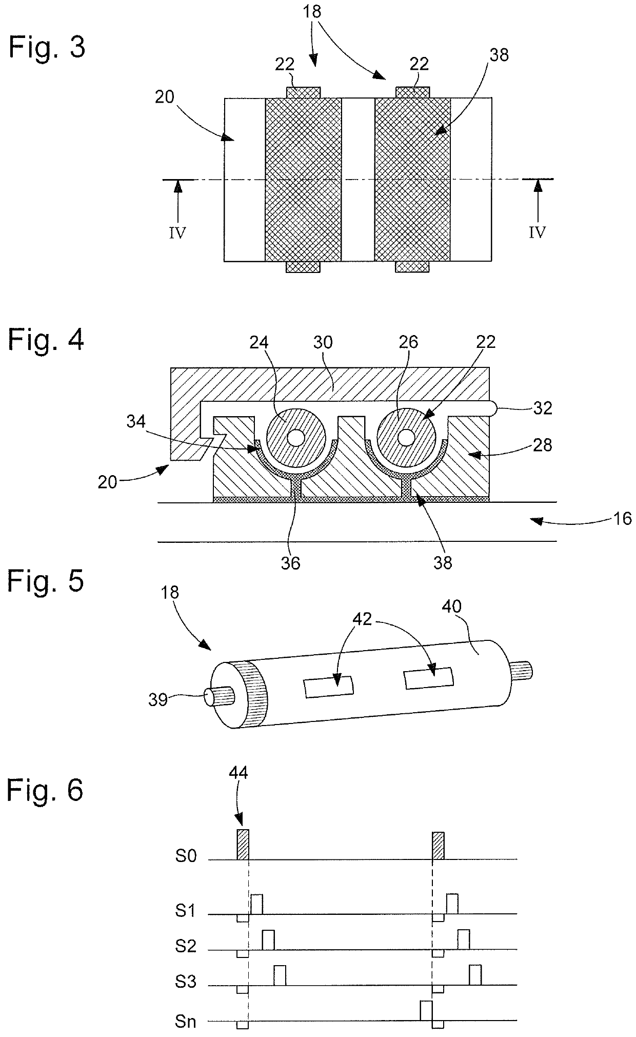
[0044]According to this first embodiment, the capacitive coupling means 20 are formed by a part for separating the strands 22. The separating part 20 is inserted between, on the one hand, the two strands 22 of the twisted pair 18 and on the other hand the communication circuit 16 of the power storage cell 12. More specifically, as shown in FIG. 4, the separating part 20 comprises a plastic base 28 on which a movable cover 30 is mounted. The movable cover 30 is, for example, mounted on the plastic base 28 via a hinge-forming means 32. The plastic base 28 defines two semi-cylindrical longitudinal cavities 34, the longitudinal direction being considered to be the direction in which the loss cable 18 extends. Inside each semi-cylindrical cavity 34, substantially in the centre of the cavity 34 and over the entire length of the base 28, a longitudinal groove 36 is made, passing through the thickness of the base 28 and opening externally thereto. The part 20 further comprises a metal coati...

second embodiment

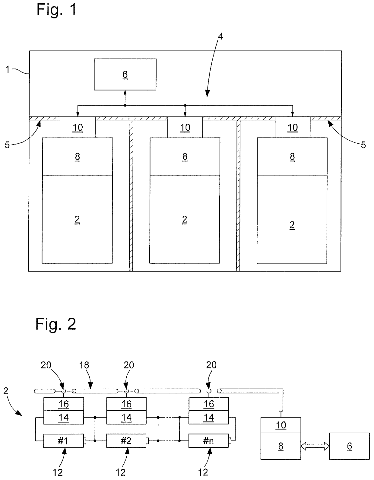
[0047]As shown in FIG. 2, according to this second embodiment, the capacitive coupling means 20 are formed by a cable pass ring 18. The ring comprises, on the inner surface thereof, a metal coating, and the loss cable 18 is inserted into the ring 20 of each power storage cell 12. The metal coating of the ring 20 is, for example, connected to the communication circuit 16 of the cell 12 via a microstrip electric line. Such an electric line acts as a guide to an electromagnetic wave propagation, and is formed by a conductive strip deposited on a dielectric substrate, the second metallised face whereof acts as a ground plane. The data signal is thus present on the metal coating of the ring 20, and the ring 20 allows the coaxial cable 18 to be coupled, by capacitive coupling, to the communication circuit 16.

[0048]Although not shown, the coaxial cable could be considered to be bonded to the battery and capacitive coupling takes place between the battery elements, i.e. between the loss cab...


PUM

PropertyMeasurementUnit
carrier frequencyaaaaaaaaaa
frequencyaaaaaaaaaa

Abstract

The system (4) is provided for managing at least one sub-assembly (2) of an electric battery. Each sub-assembly comprises a plurality of power storage cells (12). The system includes, for each power storage cell, a circuit (14) for managing the state of the cell and a communication circuit (16), which is configured such that it receives and transmits data relative to the cell. The communication circuit is configured such that it transposes, over a carrier frequency, the data to be received and transmitted, the value of said carrier frequency being greater than or equal to 1 GHz. The management system further includes, for each sub-assembly, a loss cable (18) connecting the power storage cells of said sub-assembly. The loss cable acts as a waveguide and is coupled by capacitive coupling to the communication circuit of each power storage cell.

Description

[0001]This application claims priority under 35 U.S.C. § 119 or 365 to European Application No. 18196555.9, filed Sep. 25, 2018. The entire contents of the above application(s) are incorporated herein by reference.TECHNICAL FIELD OF THE INVENTION[0002]The invention relates to a system for managing at least one sub-assembly of an electric battery.[0003]The invention further relates to an electric battery comprising the management system and at least one sub-assembly provided with a plurality of power storage cells.[0004]The electric battery is, for example, a battery intended to equip a vehicle, for example a motor vehicle, and in particular but not limited to an electric vehicle.PRIOR ART[0005]In order to be able to provide sufficient power levels, electric batteries are formed by sub-assemblies. Each of these sub-assemblies groups together a plurality of power storage cells. When using these batteries, several aspects must be checked such as, for example, maintaining an operational...

Claims


Application Information

Patent Timeline
Patent Type & Authority Patents(United States)
IPC IPC(8): H01M10/42H01M10/44
CPCH01M10/425H01M10/443H01M2010/4271H01M10/48B60L3/0046B60L58/12B60L58/18B60L58/21B60L58/22H02J2310/48H02J7/00036H04B3/52Y02T90/16H04B5/0012H02J7/0048
Inventor SCORDILIS, THIERRYSABY, JEROMECASAGRANDE, ARNAUDDE ROSA, LUCA
Owner EM MICROELECTRONIC-MARIN
Why Eureka
Try Eureka