

Micro-fabricated guidewire devices having varying diameters
a guidewire and micro-fabricated technology, applied in the direction of prosthesis, catheter, application, etc., can solve the problems of inability to manufacture guidewires and catheters with current technology machines (as described in published patents) to achieve the effect of reducing the functionality of guidewires and catheters, and reducing the risk of bleedou
Active Publication Date: 2022-08-09
SCIENTIA VASCULAR INC
View PDF471 Cites 0 Cited by
- Summary
- Abstract
- Description
- Claims
- Application Information
AI Technical Summary
Benefits of technology
The machine produces catheters and guidewires with improved flexibility, torquability, and consistency, capable of handling a variety of materials, including plastics and metals, with enhanced precision and reliability, addressing safety and performance concerns by directly controlling the critical dimension of resultant beams.
Problems solved by technology
If blood in the vessels is allowed to “leak,” direct damage can be caused to any tissue outside of the normal capillary approach contacted by the blood, and / or may result in a deadly problem of exsanguination or “bleed out”.
An aneurysm is a very fragile ballooned vessel wall which can easily be punctured if the guidewire or catheter is not precisely controlled.
The guidewires and catheters produced with current technology machines (as described in published patents) have limited functionality.
Due to the single blade design and other aspects of these existing machines, the machines lack the precision necessary to control small (sub 0.002″) features on a reliable basis.
They also lack the ability to precisely control and verify larger features, which could affect the safety and / or performance of these devices.
These machines are also only capable of working with electrically conductive stock material because the machines rely on the electrical conductivity of the stock material to determine the position of the stock relative to the cutting blade.
As the cutting machine is incapable of determining the precise diameter (at the location of the cut) of the stock material being cut, each cut is made according to a preprogrammed depth regardless of that diameter.
This is a problem because stock material is not always of a uniform shape and diameter—there are often imperfections along the length of stock that can affect both the roundness of the stock material and the diameter of the stock material at any particular location.
If the diameter of the stock is thicker than anticipated at the location of the cuts, then the resultant beam will be thicker and therefore less flexible than desired.
If the diameter of the stock is thinner than anticipated at the location of the cuts, then the resultant beam will be thinner and therefore weaker than desired.
This is problematic in terms of both safety and performance of the final product, whether it is a guidewire, catheter or other device.
Existing technology is also unable to cut any kind of non-conductive material, such as plastic.
Method used
View moreImage
Smart ImageViewing Examples

Examples
example 2
[0150]A solid mono-filament stock material that is a composite, for example, co-extruded with various polymer layers, or glass fiber filled or carbon fiber filled materials.
example 3
[0151]A solid mono-filament material that may be a polymer that has been coated over a wire such as stainless steel.
Login to View More PUM
 Abstract
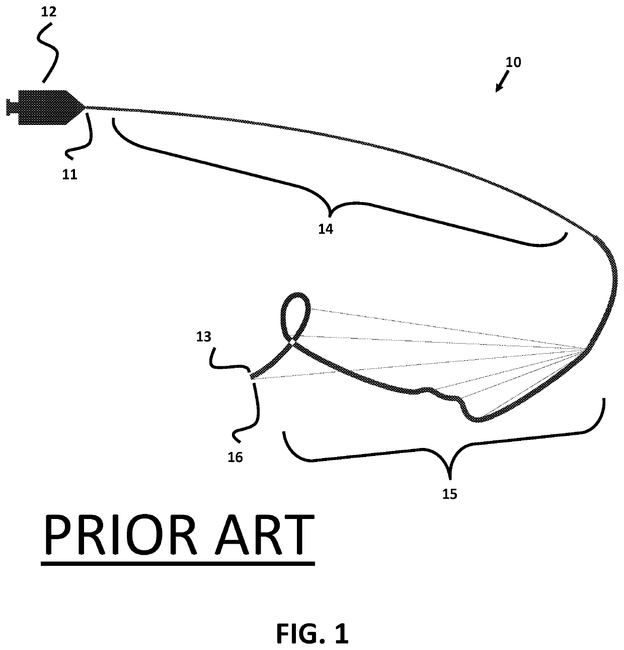
Polymer catheters and guidewires for use in intravascular surgery, and more particularly polymer catheters and guidewires micro-machined with a micro-cutting machine to provide sufficient flexibility to travel through a patient's vasculature while retaining sufficient torquability to transmit torque from a proximal end to the distal end of the catheter or guidewire, and methods of producing the same.
Description
CROSS-REFERENCES TO RELATED APPLICATIONS[0001]This application is a continuation of U.S. patent application Ser. No. 12 / 753,858, filed on Apr. 2, 2010 and titled “Micro-fabricated Guidewire Devices Having Varying Diameters,” which claims priority to and the benefit of U.S. Provisional Patent Application Ser. No. 61 / 166,480, filed on Apr. 3, 2009 and titled “Catheters and Guidewires for use in Intravascular Surgery and a Micro-cutting Machine to Make / cut the Catheters and Guidewires,” U.S. patent application Ser. No. 12 / 753,858 also being a continuation-in-part of and claiming priority to U.S. patent application Ser. No. 12 / 633,727, filed Dec. 8, 2009 and titled “Micro-cutting Machine for Forming Cuts in Products,” the entireties of each of which are incorporated herein by this reference.BACKGROUND[0002]The medical field utilizes highly flexible and torquable catheters and guidewires to perform delicate procedures deep inside the human body. Endovascular procedures typically start at...
Claims
Login to View More Application Information
Patent Timeline
 Patent Type & AuthorityPatents(United States)
IPC IPC(8): A61B5/00A61M25/00A61B18/14A61M25/09A61B17/00B26D5/20B26F1/00
CPCA61M25/0013A61B18/1492A61M25/0051A61M25/09A61B17/00234A61M25/0045A61M25/0053A61M2025/0042A61M2025/09108A61M2025/09133B26D5/20B26F1/0053B26F1/0061A61M25/0054A61M29/00A61F2250/0018A61M2025/006A61M25/0069
InventorLIPPERT, JOHNSNYDER, EDWARD J.
OwnerSCIENTIA VASCULAR INC