Proton linear accelerator system for irradiating tissue with two or more RF sources

a technology of protons and accelerators, applied in accelerators, radiation therapy, therapy, etc., can solve the problems of increasing the cost of the accelerator system, requiring an increase in the rate of rf acceleration pulses, and requiring more expensive rf sources

Active Publication Date: 2022-08-09
ADAM SA
View PDF12 Cites 2 Cited by
  • Summary
  • Abstract
  • Description
  • Claims
  • Application Information

AI Technical Summary

Benefits of technology

[0009]During operation of the system for proton therapy, the damage to surrounding tissue may be reduced by changing the beam energy, and therefore both the range of the beam and the corresponding Bragg peak. By adjusting the depth of the Bragg peak many separate Bragg peaks may be overlapped to produce an extended Bragg peak which produces a flat, or approximately flat, dose distribution which covers the tumor region. It is therefore advantageous to have a relatively small time between energy steps as this reduces the total treatment time, thereby reducing the risk of patient movement during treatment. Additionally or alternatively, the number of energy levels available for treatment may be increased, allowing a more accurate control of the spread of energy to surrounding tissues. Additionally or alternatively, movements of the tumor during treatment due to, for example patient breathing, may also be compensated for in real-time to improve the control even further. However, this does require an increase in the rate of RF acceleration pulses that need to be supplied to the cavity during operation.
[0010]In addition, providing RF compensation pulses (RF energy during the off-time of the proton beam operating cycle) may increase the RF pulse rate reaching the cavity still further. Applying RF power to the accelerator unit cavities during the proton beam off-time may reduce settling time as these RF compensation pulses may be predetermined and / or controlled to increase or maintain the temperature of the cavity.
[0011]The invention is based upon the insight that increasing the pulse rate from a RF source may considerably reduce lifetime and reliability of the RF source. In addition, the higher RF pulse rate means that a more expensive RF source may be required, increasing the cost of the accelerator system. Two distinct RF sources are provided—a first, or primary, RF energy source primarily arranged to provide RF acceleration pulses, and a second, or secondary, RF energy source primarily arranged to provide RF compensation pulses. Each RF source is operated independently, allowing higher RF pulse rates to reach the cavity, supporting a smaller time between proton beam energy pulses. In addition, the peak power requirements for the second RF energy source may, in general, be less than for the second RF energy source, allowing a less costly type to be used for the second source. The use of a first and second RF source may reduce the cavity settling time from minutes to less than 10 seconds.
[0017]The energy reaching the cavity during each successive proton beam operating cycle from the first and second RF sources is kept substantially constant. This may provide a high degree of beam stability with a low settling time, which is particularly advantageous during treatment.
[0020]Additionally, a liquid-based temperature control system may be used to further improve the temperature compensation and / or stabilization. The combination with RF temperature compensation may allow the use of a simplified temperature control system compared to conventional systems.

Problems solved by technology

However, this does require an increase in the rate of RF acceleration pulses that need to be supplied to the cavity during operation.
In addition, the higher RF pulse rate means that a more expensive RF source may be required, increasing the cost of the accelerator system.

Method used


Image

  • Proton linear accelerator system for irradiating tissue with two or more RF sources
  • Proton linear accelerator system for irradiating tissue with two or more RF sources
  • Proton linear accelerator system for irradiating tissue with two or more RF sources

Examples


Embodiment Construction

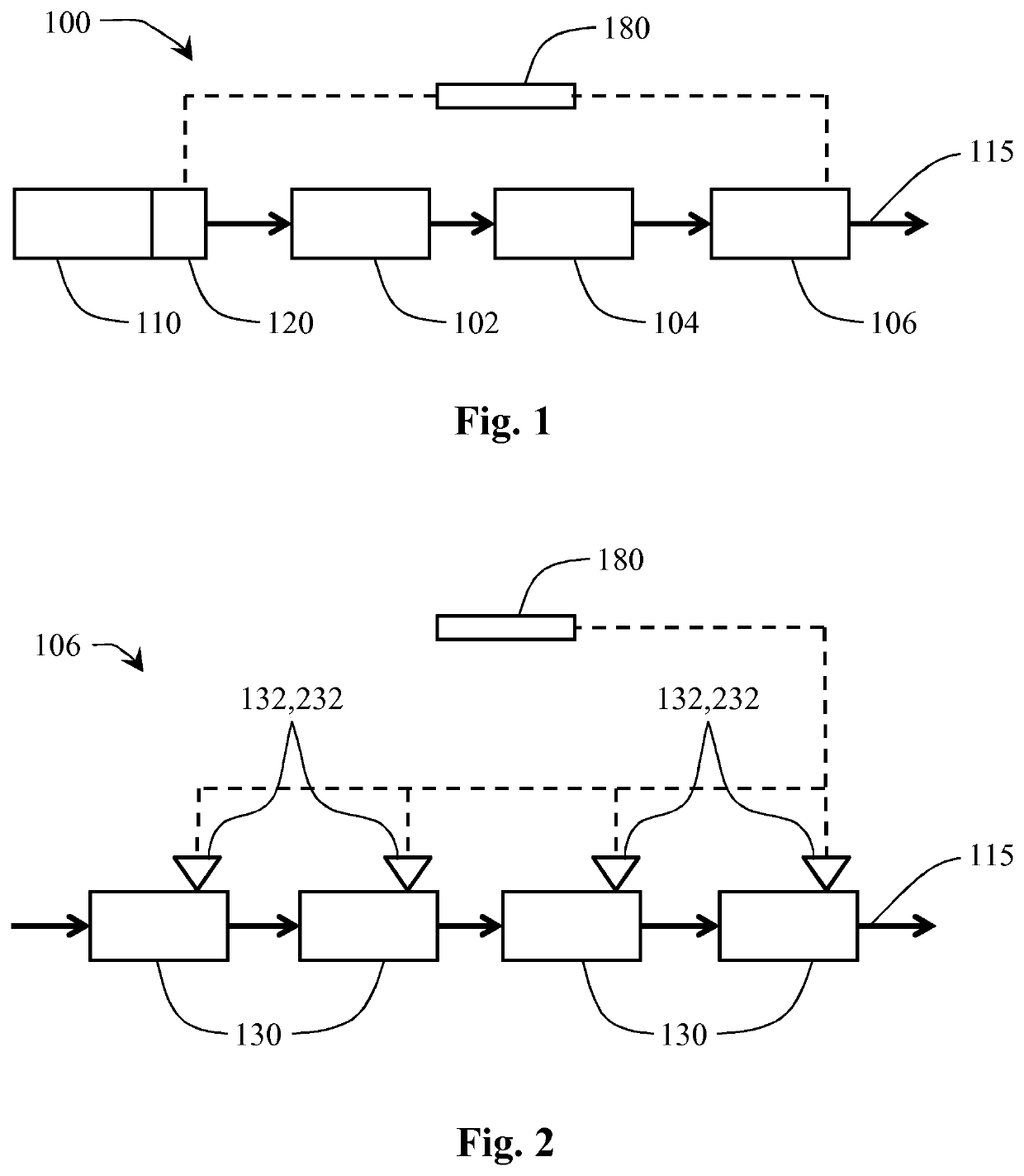
[0032]FIG. 1 schematically shows a proton linear accelerator (or linac) system 100 according to the invention. The linac system 100 comprises a proton beam source 110 for providing a proton beam 115 during operation. A beam output controller 120 is provided to determine and / or control the beam current of the proton beam exiting the source 110. The proton beam 115 exiting the beam controller 120 is a pulsed beam. It may also be advantageous to configure the beam controller 120 to vary the proton beam duty cycle 145 (depicted in FIGS. 5 and 6). The beam output controller 120 may also be configured to blank the beam for one or more proton beam duty cycles 145, 245 As depicted in FIGS. 5 and 6, the operating cycle 190 of the proton beam 115 usually comprises an on-time and an off-time—the on-time is when the proton beam 115 energy is greater than zero, and the off-time is when the proton beam 115 energy is substantially lower than the on-time energy. The proton beam duty cycle 145 is th...


PUM


Abstract

Proton beams are a promising alternative to X-rays for therapeutic purposes because they may also destroy cancer cells, but with a greatly reduced damage to healthy tissue. The energy dose in tissue may be concentrated at the tumor site by configuring the beam to position the Bragg Peak proximate the tumor. The longitudinal range of a proton beam in tissue is generally dependent upon the energy of the beam. However, after switching energies, the proton-beam system requires some time for the beam energy to stabilize before it may be used for therapy. A proton linear accelerator system is provided for irradiating tissue with an improved beam energy control, configured to provide RF energy from a first RF energy source during the on-time of the proton beam operating cycle for changing the energy of the proton beam, and to provide RF energy from a second distinct RF energy source during the off-time of the proton beam operating cycle for increasing or maintaining the temperature of the cavity. Each RF source is operated independently, allowing higher RF pulse rates to reach the cavity, supporting a smaller time between proton beam energy pulses. In addition, the peak power requirements for the second RF energy source may, in general, be less than for the second RF energy source, allowing a less costly type to be used for the second source. The use of a first and second RF source may reduce the cavity settling time from minutes to less than 10 seconds.

Description

CROSS-REFERENCE TO RELATED APPLICATIONS[0001]This application is the U.S. National Stage of International Application No. PCT / EP2019 / 060471 filed Apr. 24, 2019, which claims benefit of priority to European Patent Application No. 18169363.1 filed Apr. 25, 2018, the entire contents of which are incorporated herein by reference.FIELD OF THE INVENTIONThe invention relates to a proton linear accelerator system for irradiating tissue comprising a proton source for providing a proton beam during operation.BACKGROUND OF THE INVENTION[0002]Energetic beams, such as X-rays, have been used therapeutically for many years to damage the DNA of cancer cells and to kill them in humans and animals. However, during the treatment of tumors, the X-rays expose surrounding healthy tissues, particularly along the path of the X-rays through the body, both before (entrance dose) and after (exit dose) the tumor site. The X-ray dose is frequently sufficiently high to result in short-term side effects and may r...

Claims


Application Information

Patent Timeline
Patent Type & Authority Patents(United States)
IPC IPC(8): A61N5/10H05H7/22H05H7/02
CPCA61N5/1065H05H7/22A61N2005/1087H05H2007/025H05H2007/227A61N2005/1022H05H7/02H05H9/041A61N5/1077
Inventor NAVARRO-QUIRANTE, JOSE LUISIVANISENKO, YEVGENIY
Owner ADAM SA
Why Eureka
Try Eureka