
Device and method for monitoring multi-die power module

a power module and multi-die technology, applied in power supply testing, semiconductor operation lifetime testing, instruments, etc., can solve problems such as difficult on-line measurements

Active Publication Date: 2022-08-16
MITSUBISHI ELECTRIC CORP
View PDF4 Cites 0 Cited by
  • Summary
  • Abstract
  • Description
  • Claims
  • Application Information

AI Technical Summary

Benefits of technology

The present invention is about an online monitoring method and device that separates measurement from timing, which can be costly in a power module with multiple dies. This allows for the measurement of the threshold voltage of a single die without measuring or synchronizing the collector current, reducing the cost of implementation. The technical effect of this invention is to provide a more cost-effective and efficient way to monitor the performance of multiple dies in a power module.

Problems solved by technology

However, the presence of both the precise current measurement and the variable gate voltage makes on-line measurements challenging especially when costs are considered.

Method used


Image

  • Device and method for monitoring multi-die power module
  • Device and method for monitoring multi-die power module
  • Device and method for monitoring multi-die power module

Examples


Embodiment Construction

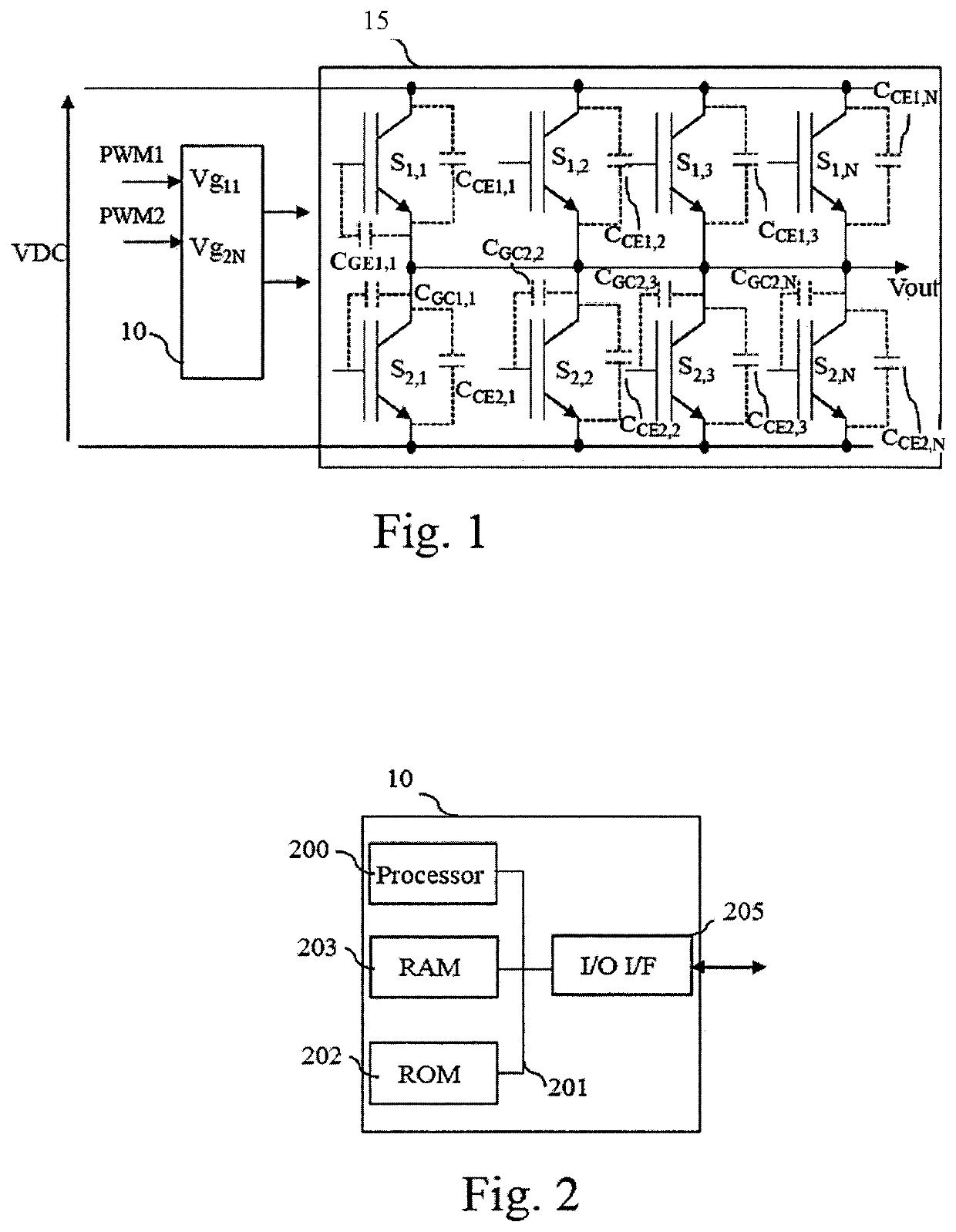
[0039]FIG. 1 represents an example of a system comprising a multi-die power module and a multi-die monitoring device according to the present invention.

[0040]The multi-die power module 15 comprises 2*N dies noted S1,1, to S1,N, S2,1 to S2,N. The dies of the multi-die power module 15 are in a half-bridge switch configuration i.e. in a classical operation mode, when the dies S1,1, to S1,N are conducting, the dies S2,1 to S2,N are not conducting and reciprocally.

[0041]The multi-die monitoring device 10 receives input signal PWM1 and PWM2 and drives the dies S1,1, to S1,N and S2,1 to S2,N through amplifiers not shown in FIG. 1.

[0042]More precisely, during normal operation, the multi-die monitoring device 10 drives the dies S1,1, to S1,N using signal PWM1 and drives the dies S2,1, to S2,N using signal PWM2.

[0043]The present invention uses the stored charge in the parasitic output capacitance of the dies as a means to measure the threshold voltage of the dies in a half-bridge configuratio...


PUM

PropertyMeasurementUnit
threshold voltageaaaaaaaaaa
voltageaaaaaaaaaa

Abstract

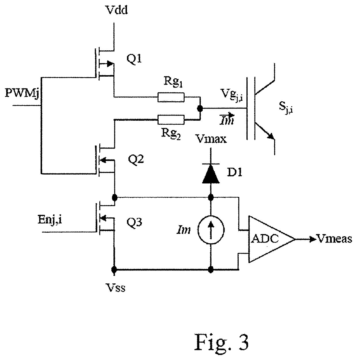
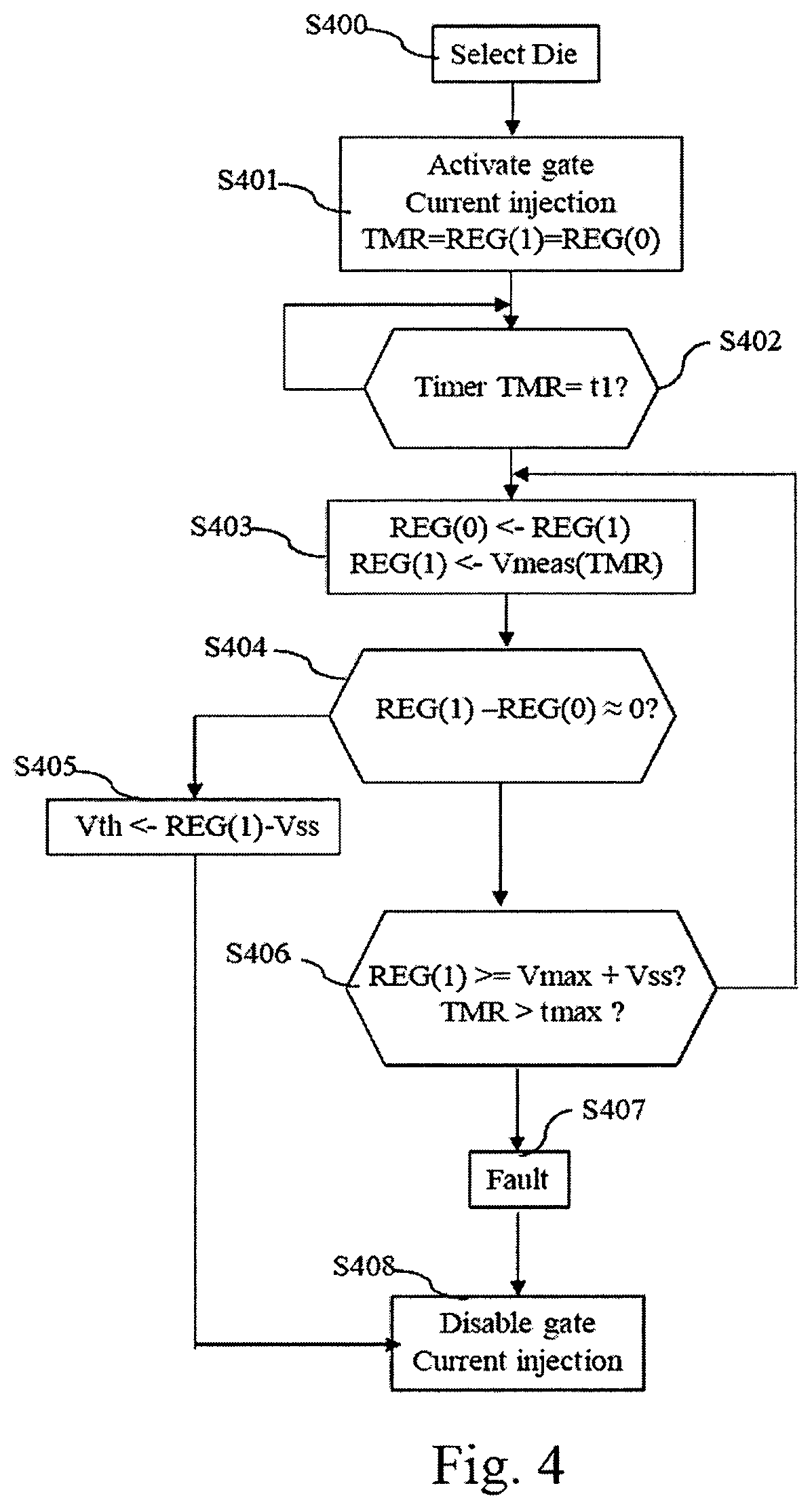
A method and device for monitoring a multi-die power module in a half-bridge switch configuration are provided. The method and device are designed to set dies in a non conductive state, select one die which is blocking a voltage, inject a current in a gate of the selected die in order to charge an input parasitic capacitance of the selected die, monitor a voltage that is representative of a voltage on the gate of the selected die, and memorize the value of the monitored voltage when the value of the monitored voltage is stabilized.

Description

TECHNICAL FIELD[0001]The present invention relates generally to a device and a method for on line monitoring a power semiconductor device.BACKGROUND ART[0002]The on-line health monitoring of power semiconductor devices requires the collection of data that are indicators of the state of health of power semiconductor devices.[0003]Typically, much developmental effort has been devoted to the monitoring of the internal junction temperature, or the on-state voltage of the power semiconductor devices.[0004]One critical, but often overlooked parameter, in voltage controlled power semiconductor devices, i.e. IGBTs or MOSFETs, is the threshold voltage.[0005]While this parameter is required to be measured at the die level after manufacturing, it is also an indicator for failure mechanisms related to the gate oxide breakdown, due to gate overvoltage, high temperature operation or other gate stresses. Furthermore, the value of the threshold voltage is also important after the packaging of the d...

Claims


Application Information

Patent Timeline
Patent Type & Authority Patents(United States)
IPC IPC(8): G01R31/28G01R31/26G01R31/27
CPCG01R31/2889G01R31/2642G01R31/275G01R31/2608G01R31/2621G01R31/42
Inventor EWANCHUK, JEFFREY
Owner MITSUBISHI ELECTRIC CORP
Learn More