
LCD device and manufacturing method thereof

Active Publication Date: 2022-09-06
TCL CHINA STAR OPTOELECTRONICS TECH CO LTD
View PDF31 Cites 0 Cited by
  • Summary
  • Abstract
  • Description
  • Claims
  • Application Information

AI Technical Summary

Benefits of technology

The present disclosure provides an LCD device and a manufacturing method thereof to solve a problem of a low yield rate of LCD panels due to poor performance of supporting posts in conventional LCD panels. The LCD device includes a temperature sensing driver chip and an LCD panel. The LCD panel includes a first substrate, a second substrate, and a liquid crystal layer disposed therebetween. The first substrate includes a plurality of supporting posts, and the temperature sensing driver chip is configured to sense changes in temperature and outputs a voltage signal according to the changes in temperature. A side of at least one of the supporting posts is provided with a control electrode, and the control electrode is connected to the temperature sensing driver chip and is configured to control heights of the supporting posts. A plurality of organic material spheres are disposed in at least one of the supporting posts. The technical effect of this patent is to enhance the performance of the supporting posts by controlling the heights of the supporting posts through the control electrode and improving stress tolerance of the supporting posts through the organic material spheres.

Problems solved by technology

Consequently, the supporting posts are difficult to test, thereby reducing a yield rate of the LCD panels.
As a result, there is a technical problem of a low yield rate of LCD panels due to poor performance of supporting posts in conventional LCD panels.

Method used


Image

  • LCD device and manufacturing method thereof
  • LCD device and manufacturing method thereof
  • LCD device and manufacturing method thereof

Examples


Embodiment Construction

[0041]An LCD device and a manufacturing method thereof of the present disclosure are described below in detail with reference to accompanying drawings to make objectives, technical solutions, and effectiveness of the present disclosure clearer and easier to be understood. It should be noted that described embodiments are merely used to construct the present disclosure and are not intended to limit the present disclosure.

[0042]An embodiment of the present disclosure can solve a technical problem of a low yield rate of LCD panels due to poor performance of supporting posts in conventional LCD panels.

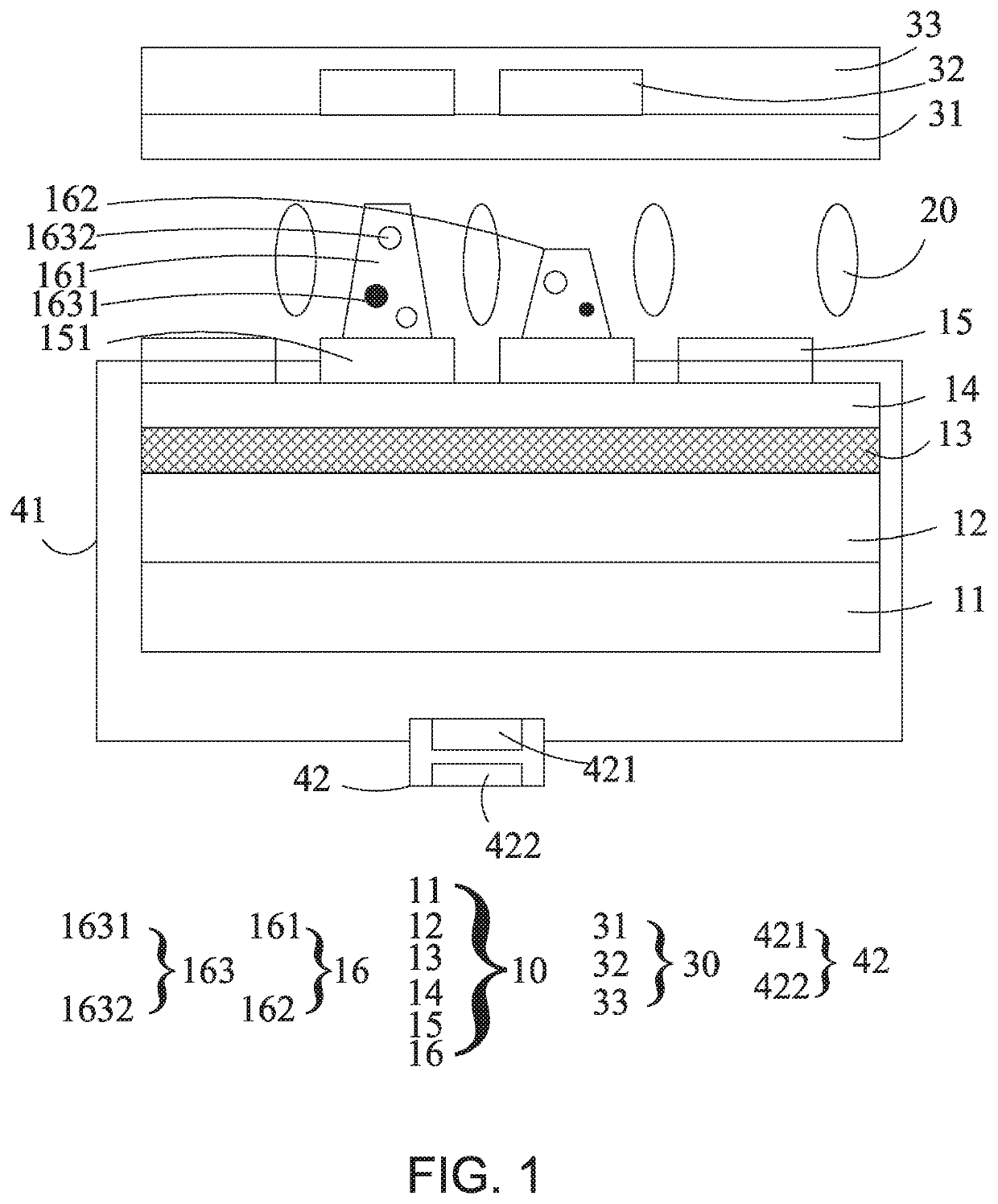
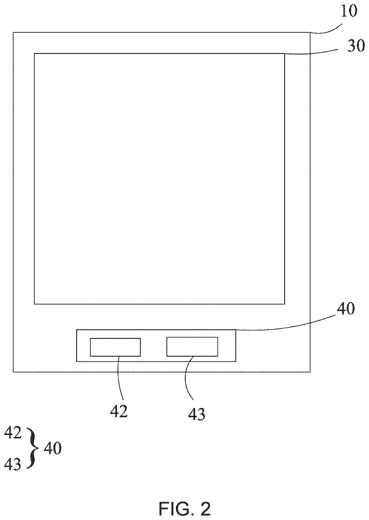
[0043]As shown in FIG. 1, an embodiment of the present disclosure provides an LCD device, including:

[0044]an LCD panel, wherein the LCD panel includes a first substrate 10, a second substrate 30, and a liquid crystal layer 20 disposed therebetween, and the first substrate 10 includes a plurality of supporting posts 16; and

[0045]a temperature sensing driver chip 42, wherein the temperature ...


PUM


Abstract

The disclosure provides a liquid crystal display (LCD) device and a manufacturing method thereof. A temperature sensing driver chip is disposed in the LCD device and can output a voltage signal to a control electrode according to changes in temperature. Therefore, an electric field is formed between the control electrode and a common electrode. Heights of a plurality of supporting posts can be changed by the electric field to control stretching and shrinking of the control electrode, thereby improving performance of the supporting posts. Thus, a plurality of organic material spheres disposed in the supporting posts can improve stress tolerance of the supporting posts, thereby further improving performance of the supporting posts.

Description

RELATED APPLICATIONS[0001]This application is a National Phase of PCT Patent Application No. PCT / CN2020 / 070646 having International filing date of Jan. 7, 2020, which claims the benefit of priority of Chinese Patent Application No. 201911354288.1 filed on Dec. 25, 2019. The contents of the above applications are all incorporated by reference as if fully set forth herein in their entirety.FIELD AND BACKGROUND OF THE INVENTION[0002]The present disclosure relates to the field of display technologies, and more particularly, relates to a liquid crystal display (LCD) device and a manufacturing method thereof.[0003]In LCD panels, a liquid crystal cell is supported by multiple supporting posts to maintain thickness uniformity. However, when display panels are tested, requirements for the supporting posts are opposite in different testing processes. For example, a high elastic recovery rate of the supporting posts is required during a high-temperature test, while a low elastic recovery rate ...

Claims


Application Information

Patent Timeline
IPC IPC(8): G02F1/1339G02F1/1333G02F1/1343
CPCG02F1/13394G02F1/13396G02F1/13398G02F1/13439G02F1/133382G02F1/134309G02F1/1343
Inventor SHAO, YUANYAN, CHUNQIUCHEN, HSIAOHSIEN
Owner TCL CHINA STAR OPTOELECTRONICS TECH CO LTD
Learn More